Functional graphene-polymer nanocomposites for gas barrier applications

a graphene-polymer nanocomposit and functional technology, applied in the direction of non-metal conductors, separation processes, conductors, etc., can solve the problems of insufficient nanoparticle dispersion, easy outpacing earlier attempts, and unparallel performance improvement, so as to improve not only the gas barrier properties of polymer materials, improve the mechanical (strength, toughness, modulus) and thermal stability and improve the gas barrier properties of the polymer composi

Inactive Publication Date: 2010-04-22
THE TRUSTEES FOR PRINCETON UNIV
View PDF42 Cites 150 Cited by
  • Summary
  • Abstract
  • Description
  • Claims
  • Application Information

AI Technical Summary

Benefits of technology

[0013]It is another object of the present invention to provide a nano filler material based on modified graphite that improves the gas barrier properties of polymer materials.
[0014]It is another object of the present invention to provide a nano filler material based on modified graphite that improves not only the gas barrier properties of polymer materials but simultaneously improves the mechanical (strength, toughness, modulus) and thermal stability of the polymer composite.
[0015]It is another object of the present invention to provide a nano filler material based on modified graphite that improves not only the gas barrier properties of polymer materials but simultaneously improves the electrical conductivity of the polymer composite.

Problems solved by technology
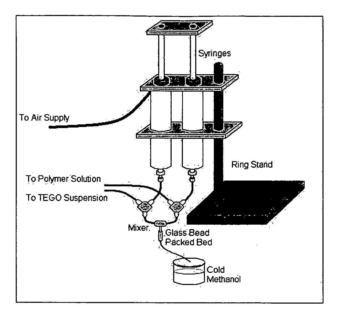
The incorporation of these sub-micron fillers in polymers, known as ‘nanocomposites’, has produced unparalleled performance improvements, easily outpacing earlier attempts.
Initial attempts at producing nanoparticle-filled polymer composites often resulted in materials with inadequate nanoparticle dispersion and degraded mechanical properties.
Several problems remain that affect the development of NCs with consistent properties that are viable for use in real world applications: (1) many of the nanoparticles used are expensive (e.g., CNTs); (2) often chemical or mechanical manipulations must be performed to achieve good dispersion that are impractical for large-scale commercial production; and (3) problems of the interfacial energy mismatch of inorganic nanofillers with hydrocarbon polymer matrix phases result in processing and mechanical property difficulties.
Recent studies point out that the hydrophilicity of clays makes them incompatible with most polymers, which are hydrophobic.
Such clays are called “organoclays.” These materials have suffered from the cost of the added interfacial modifiers and the instability of these modifiers under processing conditions.
In addition, it has been difficult to homogeneously disperse these organoclays in polymer matrices.
As a nanofiller, CNTs have several limitations, one of which is their cost of production.
Since they are made in a gas-phase process, the production costs are more expensive than solution-based processes operating at high density.
The production of single wall carbon nanotubes (SWCNTs) requires the addition of metal catalysts that must be removed to produce pure SWCNT materials, or results in the presence of heavy metal contaminants in the final materials if not removed.
Even though graphene sheets have the same sp2 carbon honey comb structure as carbon nanotubes (CNTs), until now, it has not been possible to effectively produce the highly dispersed, thin sheets needed to make graphene applications in polymer nanocomposites, in particular for gas barrier applications, possible.

Method used


Image

  • Functional graphene-polymer nanocomposites for gas barrier applications
  • Functional graphene-polymer nanocomposites for gas barrier applications
  • Functional graphene-polymer nanocomposites for gas barrier applications

Examples


example 1

[0180]Graphite oxide was prepared from graphite by a process of oxidation and intercalation, referred to as the Staudenmaier method. The method uses a combination of oxidizers and intercalants: sulfuric acid, nitric acid and potassium chlorate under controlled temperature conditions. Ratios of graphite to potassium chlorate in the range of 1:8 to 1:20 (wt / wt) are preferred. Ratios of sulfuric to nitric acid from 5:1 to 1:1 are preferred. The Staudenmaier method is the preferred oxidation procedure.

[0181]In this example, 5 g graphite flake with a 400 μm average flake size (Asbury Carbon, Asbury, N.J.) was added to an ice-cooled solution containing 85 ml sulfuric acid and 45 ml nitric acid. This was followed by the addition of 55 g potassium chlorate over 20 minutes such that the temperature did not exceed 20° C. After this oxidation / intercalation process proceeded for 96 hours, the reaction mixture was poured into 7 l of deionized water and filtered using an aspirator. The oxidized g...

example 2

[0182]In preparing thermally exfoliated graphite oxide (FGS), graphite oxide (0.2 g) was placed in a ceramic boat and inserted into a 25 mm ID, 1.3 m long quartz tube that was sealed at one end. The other end of the quartz tube was closed using a rubber stopper. An argon (Ar) inlet and thermocouple were then inserted through the rubber stopper. The sample was flushed with Ar for 10 minutes; the quartz tube was then quickly inserted into a preheated Lindberg tube furnace and heated for 30 seconds.

example 3

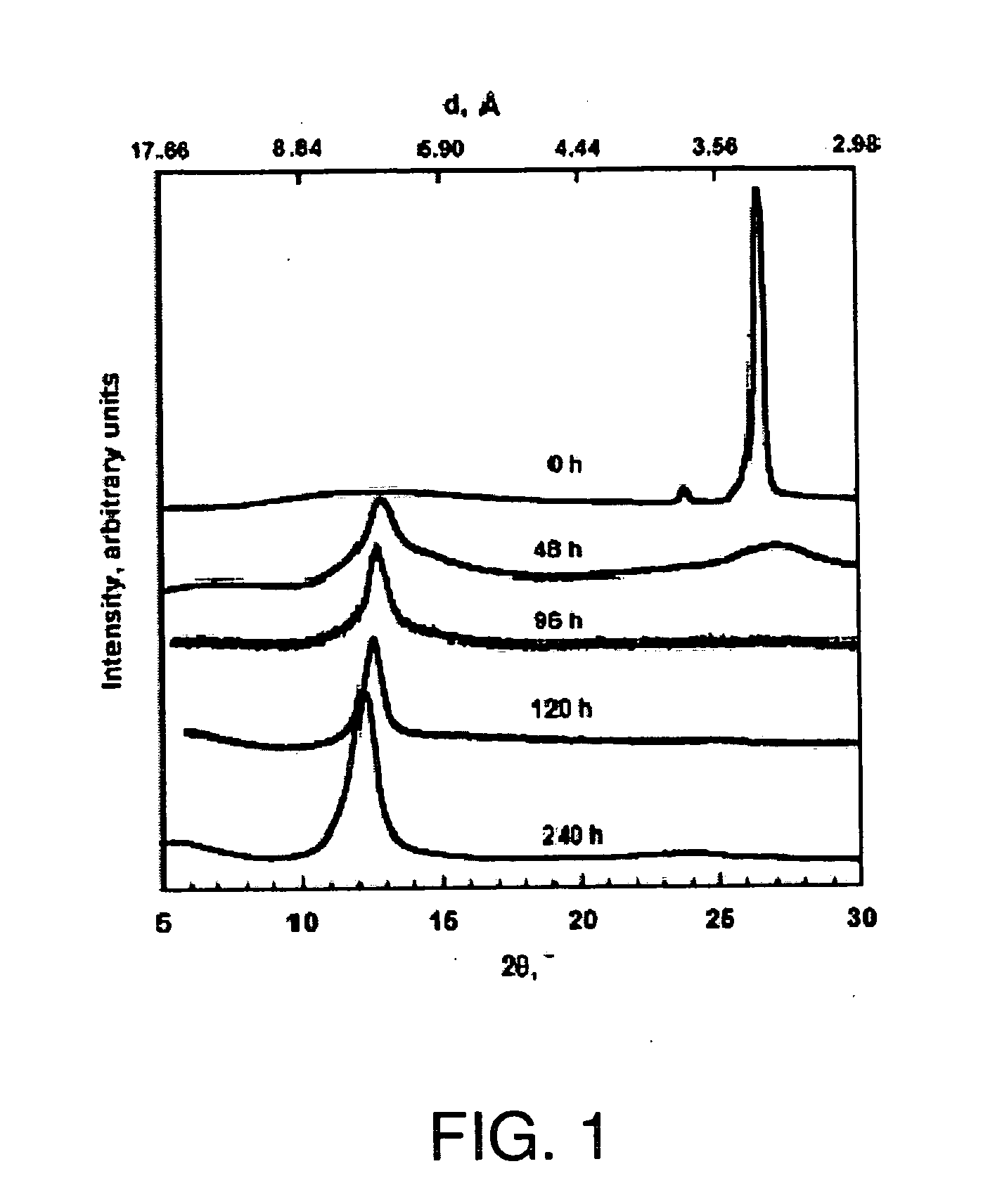
[0183]XRD patterns of graphite, GO, and FGS were recorded in a Rigaku MiniFlex diffractometer with Cu Kα radiation. Initial, final and step angles were 5, 30 and 0.02, respectively. The surface area of FGS was measured by nitrogen adsorption at 77K using a Micromeritics FlowSorb apparatus with a mixture of N2 and He 30 / 70 by volume as the carrier gas. High-resolution XPS spectra were obtained using an Omicron ESCA Probe (Germany). Samples were de-gassed overnight within the XPS chamber (10-3 mbar) prior to analysis of the sample. Data were collected using 15 kV and 20 mA power at 10-9 mbar vacuum. The raw XPS data were analyzed to determine peak locations and areas in relation to specific binding energies that best fit the experimental data. The main C—C peak (C1s) at 284.6 eV was observed. An additional photoemission present at higher binding energy peaks at 286.1 eV represented —C—O— or C—O—C bonding.


PUM

PropertyMeasurementUnit
densityaaaaaaaaaa
aspect ratioaaaaaaaaaa
temperatureaaaaaaaaaa

Abstract

A gas diffusion barrier contains a polymer matrix and a functional graphene which displays no signature of graphite and / or graphite oxide, as determined by X-ray diffraction.

Description

BACKGROUND OF THE INVENTION[0001]1. Field of the Invention[0002]The present invention relates to a nanocomposite containing functional graphene and a polymer, the method of making and use of the nanocomposite, in particular for barrier membranes such as gas diffusion membranes.[0003]2. Description of the Related Art[0004]Over the past five decades, industrial scale ‘composite materials’ have been produced by adding numerous minerals and metals to thermosetting, thermoplastic and elastomeric polymers. Donnet, J. B., Nano and microcomposites of polymers elastomers and their reinforcement. Composites Science and Technology 2003, 63, (8), 1085-1088. As compared to the bulk polymers, these composites have shown moderate mechanical performance improvements in properties such as Young's modulus, tensile strength, abrasion resistance and storage modulus. However, recent advances in nanoscale particle synthesis have dramatically accelerated the growth of the composite industry. The capacity ...

Claims


Application Information

Patent Timeline
Patent Type & Authority Applications(United States)
IPC IPC(8): H01B1/24
CPCB82Y30/00C01B31/0423C01B31/043C01P2004/24C01P2004/54Y10S95/903C01P2006/62C08J5/005C08J2300/00C08K3/04C08K2201/008C01P2006/10C01B32/225C01B32/23B82B3/00C08J5/10H01B1/24
Inventor PRUD'HOMME, ROBERT K.O'NEIL, CHRISTOPHER D.OZBAS, BULENTAKSAY, ILHAN A.REGISTER, RICHARD A.ADAMSON, DOUGLAS H.
Owner THE TRUSTEES FOR PRINCETON UNIV
Why Eureka
Try Eureka