Miniaturized, low power, wireless transmitter and receiver with on-chip antenna, and wireless coupling of on-chip and off-chip antenna
a technology of on-chip antennas and wireless transmitters, applied in the direction of antennas, bulk negative resistance effect devices, transmission, etc., can solve the problems of increasing cost and overall power consumption, low q passives, and low noise of on-chip antennas, so as to achieve 5 mw of power or less, excellent sensitivity, and low resistivity
- Summary
- Abstract
- Description
- Claims
- Application Information
AI Technical Summary
Benefits of technology
Problems solved by technology
Method used
Image
Examples
first embodiment
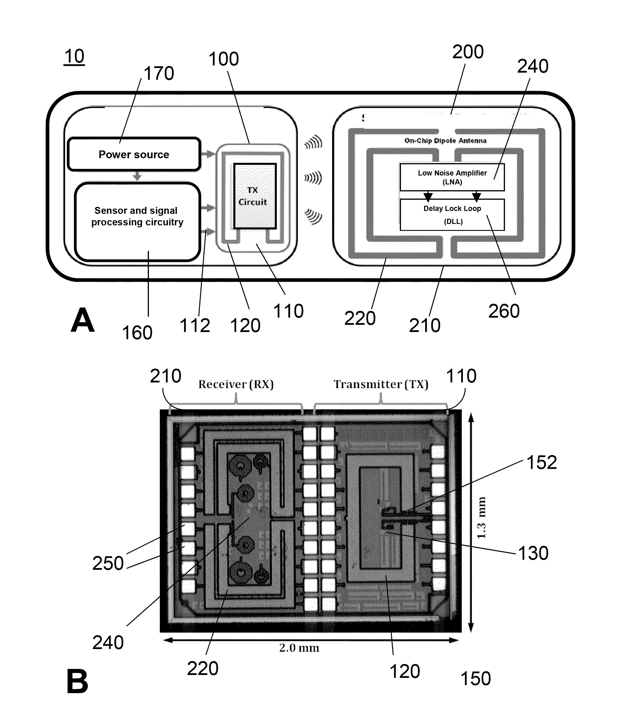
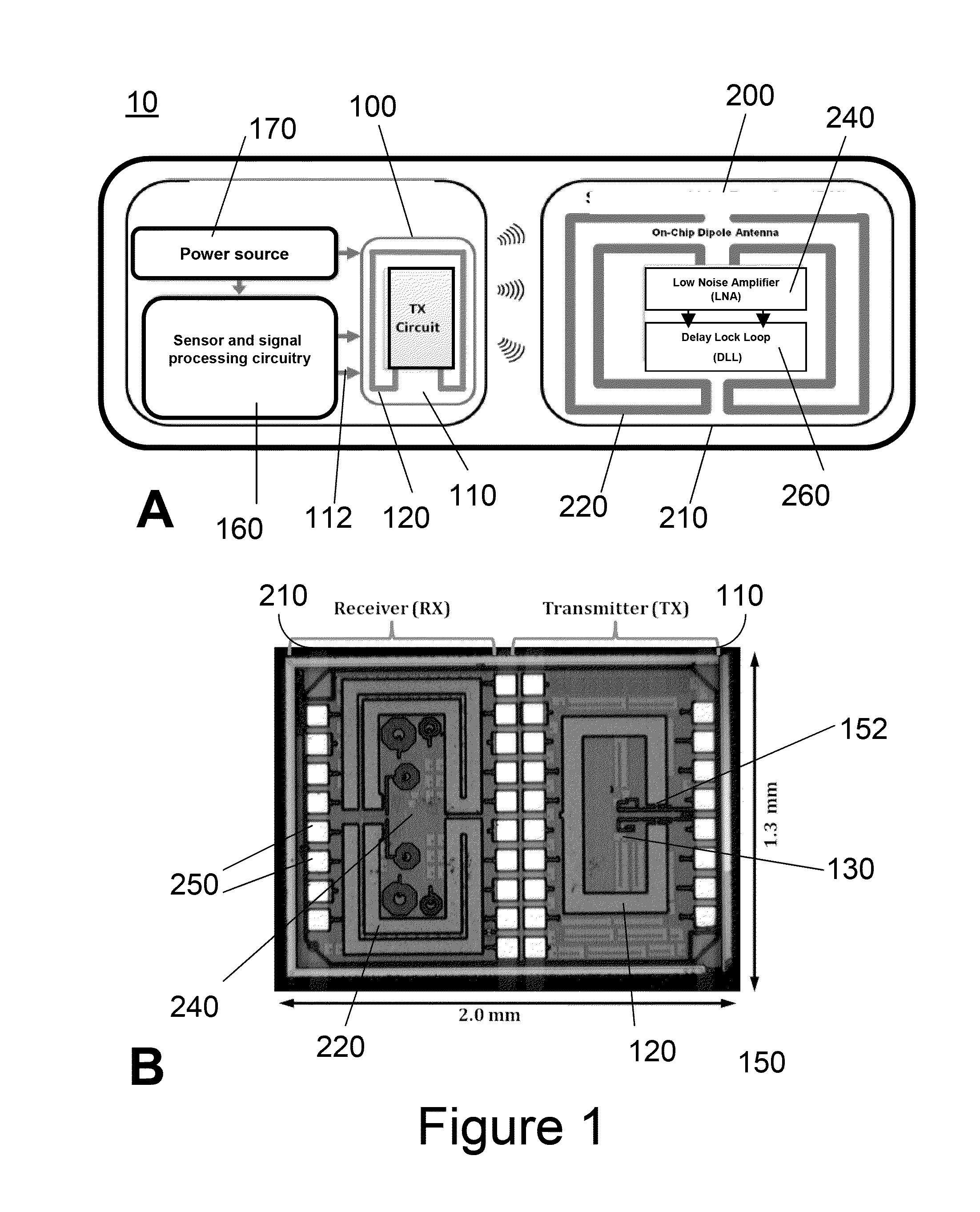
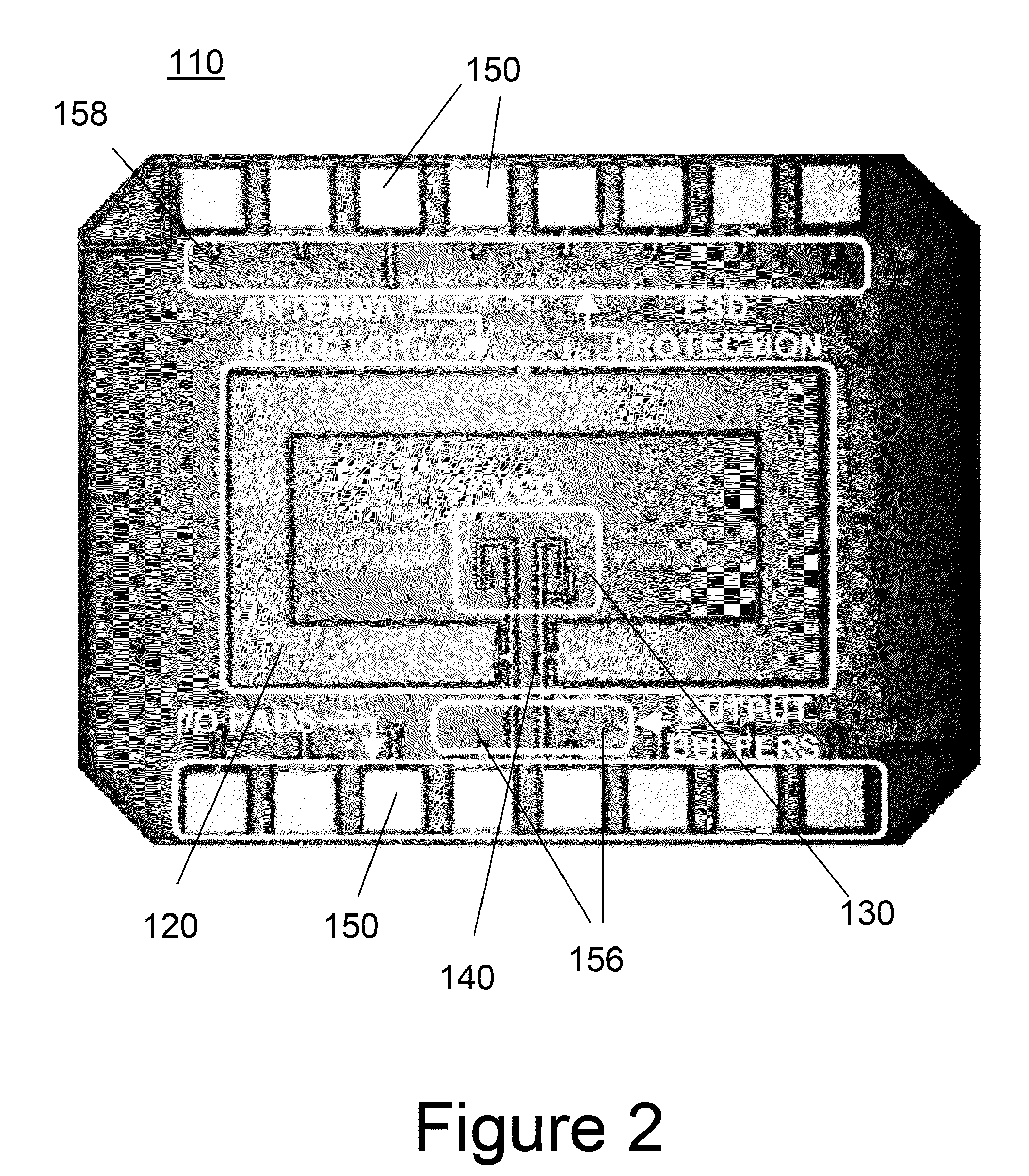
[0069]As illustrated in FIG. 1A, a transmitter / receiver system 10 according to the present invention comprises a CMOS integrated circuit which comprises a monolithically integrated circuit (transmitter chip) 100 comprising a transmitter 110, and a monolithically integrated circuit (receiver chip) 200 comprising a receiver 210. In this exemplary embodiment, the transmitter 100 comprises a data signal source 160, which may be on a separate chip or monolithically integrated with the transmitter 110. The signal source 160 comprises, by way of example only, a low voltage sensor such as a biomedical sensor, integrated with signal processing electronics, and provided on a separate substrate. The data signal source generates a suitable low voltage output, which directly feeds the input 112 of the oscillator transmitter circuit 110. The oscillator transmitter circuit 110 comprises an on-chip loop antenna 120, as will be described in detail below (page 14). Also shown in FIG. 1A is an on-chip...
second embodiment
[0087]A photomicrograph of a monolithically integrated RF transmitter circuit 300 according to the present invention comprises an on-chip folded dipole antenna 320 is shown in FIG. 7. The RF RX circuit 300 comprises an on-chip antenna 320 monolithically integrated with a differential LNA 340 and DLL demodulator 360, which may be realized in a standard 0.13 μm CMOS process technology on a low resistivity 13.5 Ω-cm silicon substrate. FIG. 8 shows a schematic of the antenna geometry used for simulations and placement of the LNA and DLL demodulator within the area defined by the folded dipole antenna. The front end of the receiver is a low power, high gain LNA that is conjugately matched to an on-chip antenna, and designed to reject noise and improve received signal strength. The impedances of the on-chip antenna 320 and differential LNA are conjugately matched over a wide frequency range through the co-design of the circuits and antenna for simultaneous low noise and input power matchi...
PUM
 Abstract
Description
Claims
Application Information
 - R&D
- Intellectual Property
- Life Sciences
- Materials
- Tech Scout
- Unparalleled Data Quality
- Higher Quality Content
- 60% Fewer Hallucinations
Browse by: Latest US Patents, China's latest patents, Technical Efficacy Thesaurus, Application Domain, Technology Topic, Popular Technical Reports.
© 2025 PatSnap. All rights reserved.Legal|Privacy policy|Modern Slavery Act Transparency Statement|Sitemap|About US| Contact US: help@patsnap.com


