
Nitrogenous heterocyclic derivative and organic electroluminescence device making use of the same

a technology of nitrogen heterocyclic derivatives and organic electroluminescence devices, which is applied in the direction of luminescent compositions, thermoelectric devices, organic chemistry, etc., can solve the problems of not being put to practical use, notably deteriorating characteristics, and short durability, so as to improve the current efficiency and enhance the light-emitting luminance

Active Publication Date: 2010-05-06
IDEMITSU KOSAN CO LTD
View PDF6 Cites 405 Cited by
  • Summary
  • Abstract
  • Description
  • Claims
  • Application Information

AI Technical Summary

Benefits of technology

[0073]A content of the phosphorescent dopant in the light emitting layer shall not specifically be restricted, and it can suitably be selected according to the purposes. It is, for example, 0.1 to 70 mass %, preferably 1 to 30 mass %. If a content of the phosphorescent dopant is less than 0.1 mass %, light emission is faint, and an addition effect thereof is not sufficiently exhibited. On the other hand, if it exceeds 70 mass %, a phenomenon called concentration quenching is markedly brought about, and the device performance is reduced.
[0088]To be more specific, the preferred reducing dopant includes at least one alkali metal selected from the group consisting of Na (work function: 2.36 eV), K (work function: 2.28 eV), Rb (work function: 2.16 eV) and Cs (work function: 1.95 eV) and at least one alkaline earth metal selected from the group consisting of Ca (work function: 2.9 eV), Sr (work function: 2.0 to 2.5 eV) and Ba (work function: 2.52 eV), and the compounds having a work function of 2.9 eV or less are particularly preferred. Among them, the preferred reducing dopant is at least one alkali metal selected from the group consisting of K, Rb and Cs, the more preferred reducing dopant is Rb or Cs, and the most preferred reducing dopant is Cs. The above alkali metals have a particularly high reducing ability, and addition of a relatively small amount thereof to the electron injecting zone makes it possible to raise a light emitting luminance in the organic EL device and extend a lifetime thereof. The combination of two or more kinds of the above alkali metals is preferred as the reducing dopant having a work function of 2.9 eV or less, and particularly preferred is the combination containing Cs, for example, the combination of Cs with Na, Cs with K, Cs with Rb or Cs with Na and K. Containing Cs in combination makes it possible to efficiently exhibit the reducing ability, and addition thereof to the electron injecting zone makes it possible to enhance a light emitting luminance in the organic EL device and extend a lifetime thereof.
[0089]In the present invention, an electron injecting layer constituted from an insulator or a semiconductor may further be provided between the cathode and the organic layer. In this case, an electric current can effectively be prevented from leaking to enhance the electron injecting property. Preferably used as the above insulator is at least one metal compound selected from the group consisting of alkali metal chalcogenides, alkaline earth metal chalcogenides, halides of alkali metals and halides of alkaline earth metals. If the electron injecting layer is constituted from the above alkali metal chalcogenides and the like, it is preferred from the viewpoint that the electron injecting property can further be enhanced. To be specific, the preferred alkali metal chalcogenides include, for example, Li2O, K2O, Na2S, Na2Se and Na2O, and the preferred alkaline earth metal chalcogenides include, for example, CaO, BaO, SrO, BeO, BaS and CaSe. Also, the preferred halides of alkali metals include, for example, LiF, NaF, KF, LiCl, KCl and NaCl. Further, the preferred halides of alkaline earth metals include, for example, fluorides such as CaF2, BaF2, SrF2, MgF2 and BeF2 and halides other than the fluorides.
[0104]The cathode is constituted from metal, and therefore the vapor deposition method and the sputtering method can be used. However, the vacuum vapor deposition method is preferred in order to protect the organic substance layer of the base from being damaged in making the film.

Problems solved by technology

Further, they are notably deteriorated in characteristics and therefore have not come to be put to practical use.
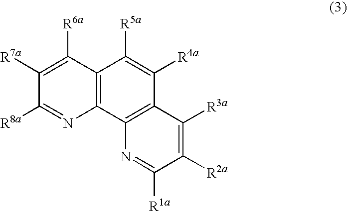
In order to solve the above problems, a specific phenanthroline derivative is used for an electron transporting material in, for example, a patent document 1 and shows a high current efficiency, but involved therein are the problems that it is crystallized by applying current for a long time and that it has a markedly short durability.

Method used


Image

  • Nitrogenous heterocyclic derivative and organic electroluminescence device making use of the same
  • Nitrogenous heterocyclic derivative and organic electroluminescence device making use of the same
  • Nitrogenous heterocyclic derivative and organic electroluminescence device making use of the same

Examples


synthetic example 1

(1-1) Synthesis of Intermediate 1

[0110]

[0111]A 500 mL three neck flask was charged with 4.8 g (24 mmol) of 4-bromoacetophenone, 10 g (29 mmol) of 10-naphthalene-2-yl-anthracene-9-boronic acid, 0.55 g (0.5 mmol) of tetrakistriphenylphosphinepalladium (0), 100 mL of 1,2-dimethoxyethane and 45 mL of a 2M sodium carbonate aqueous solution under argon flow, and the mixture was heated and refluxed for 8 hours. After finishing the reaction, the organic layer was washed with water and dried on magnesium sulfate, and the solvent was removed by distillation by means of a rotary evaporator. The resulting crude crystal was recrystallized from ethanol to obtain 8.5 g (white crystal, yield: 70%) of the targeted intermediate 1.

(1-2) Synthesis of Compound (1)

[0112]

[0113]The intermediate 1 4.0 g (9.5 mmol), 8-aminoquinoline-7-carboaldehyde 1.7 g (9.9 mmol) and ethanol 40 mL were added and dissolved by heating under argon atmosphere. A saturated potassium hydroxide ethanol solution 10 mL was dropwise...

synthetic example 2

(2-1) Synthesis of Intermediate 2

[0114]

[0115]An intermediate 2 was obtained by carrying out the same operation, except that in Synthetic Example 1 (1-1), 3-bromoacetophenone was used in place of 4-bromoacetophenone. Yield: 60%.

(2-2) Synthesis of Compound (2)

[0116]

[0117]A compound (2) was obtained by carrying out the same operation, except that in Synthetic Example 2 (1-2), the intermediate 2 was used in place of the intermediate 1. This product was measured by FD-MS (field desorption mass spectrum), whereby it was identified as the compound (2). Yield: 50%.

example 1

Production of Organic EL Device in which the Compound of the Present Invention is Used in an Electron Injecting Layer

[0118]A glass substrate (manufactured by Geomatech Co., Ltd.) of 25 mm×75 mm×1.1 mm thickness equipped with an ITO transparent electrode (anode) was subjected to supersonic wave washing in isopropyl alcohol for 5 minutes and then to UV ozone washing for 30 minutes. After washed, the glass substrate equipped with an ITO transparent electrode line was loaded in a substrate holder of a vacuum vapor deposition apparatus, and a N,N′-bis(N,N′-diphenyl-4-aminophenyl)-N,N-diphenyl-4,4′-diamino-1,1′-biphenyl film (hereinafter abbreviated as a “TPD232 film”) having a film thickness of 60 nm was first formed on a face of a side at which the transparent electrode line was formed so that it covers the transparent electrode described above. This TPD232 film functions as a hole injecting layer. After forming the TPD232 film, a 4,4′-bis[N-(1-naphthyl)-N-phenylamino]biphenyl film (her...


PUM

PropertyMeasurementUnit
transmittanceaaaaaaaaaa
work functionaaaaaaaaaa
transmittanceaaaaaaaaaa

Abstract

A nitrogenous heterocyclic derivative of specified structure; and an organic electroluminescence device comprising a negative electrode and a positive electrode and, interposed therebetween, one or two or more organic thin-film layers having at least a light emitting layer, wherein at least one of the organic thin-film layers contains the above nitrogenous heterocyclic derivative alone or as a component of mixture. Thus, there is provided an organic electroluminescence device capable of blue light emission realizing high emission brightness and luminous efficiency, and provided a novel nitrogenous heterocyclic derivative for realization of such an organic electroluminescence device.

Description

BACKGROUND OF THE INVENTION[0001]The present invention relates to a novel nitrogen-containing heterocyclic derivative, a material for an organic electroluminescence (EL) device obtained by using the same and an organic electroluminescence device comprising the same, specifically to a nitrogen-containing heterocyclic derivative which is useful as a constitutional component for an organic EL device, a material for an organic EL device obtained by using the same and an organic electroluminescence device which is enhanced in a light emitting luminance and a current efficiency while operated at a low voltage by using the above nitrogen-containing heterocyclic derivative for at least one layer in an organic compound layer.RELATED ART[0002]An organic electroluminescence (EL) device obtained by using organic materials is assumed to be promising in uses of an inexpensive large area full color display device of a solid light emitting type, and a lot of developments therefor has been carried o...

Claims


Application Information

Patent Timeline
Patent Type & Authority Applications(United States)
IPC IPC(8): H01L51/50C07D471/04
CPCC07D471/04C09K11/06C09K2211/1011C09K2211/1029C09K2211/1044H01L51/0058H01L51/006H01L51/0067H01L51/0072H01L51/5012H01L51/5048H01L51/5092H05B33/14H10K85/626H10K85/633H10K85/654H10K85/6572H10K50/11H10K50/14H10K50/171
Inventor HOSOKAWA, CHISHIOYAMAMOTO, HIROSHIARAKANE, TAKASHI
Owner IDEMITSU KOSAN CO LTD
Learn More