Platinum-Based Electrocatalysts Synthesized by Depositing Contiguous Adlayers on Carbon Nanostructures

a carbon nanostructure, carbon nanotechnology, applied in the direction of catalyst activation/preparation, metal/metal-oxide/metal-hydroxide catalyst, etc., can solve the problem of limited charge storage capacity, inability to achieve high power density, and difficulty for ions in the electrolyte to access intrapore surfaces, etc. problem, to achieve the effect of improving the stability, long-term viability and activity of the surface layer, and facilitating more efficient and cost-effective electrochemical energy conversion

Inactive Publication Date: 2010-07-15
BROOKHAVEN SCI ASSOCS
View PDF22 Cites 94 Cited by
  • Summary
  • Abstract
  • Description
  • Claims
  • Application Information

AI Technical Summary

Benefits of technology

[0026]In yet another embodiment deposition of a noble metal shell layer may be preceded by a coating comprising a transition metal such as Cu, nickel (Ni), or zinc (Zn). Initial shell formation is followed by the deposition of a catalytically active surface layer. This is preferably accomplished by displacement of a quasi-underpotentially deposited transition metal such as a Cu adlayer by a more noble metal. The catalytically active surface layer is preferably Pt or a Pt alloy due to their high catalytic activity. The inclusion of a shell layer between the underlying nanostructured carbon and the catalytically active surface layer improves the stability, long term viability, and activity of the surface layer.
[0027]Another embodiment relates to the use of carbon nanostructures coated with a contiguous thin film of a catalytically active surface layer as electrodes. Still another embodiment relates to electrodes comprising carbon nanostructures having a shell of a transition metal coated with a contiguous thin film of a catalytically active surface layer. Such coated nanostructures facilitate more efficient and cost-effective electrochemical energy conversion in electrochemical devices fabricated from these structures. Such an electrode may be used, for example, in energy conversion devices such as fuel cells, batteries, capacitors, and supercapacitors.

Problems solved by technology
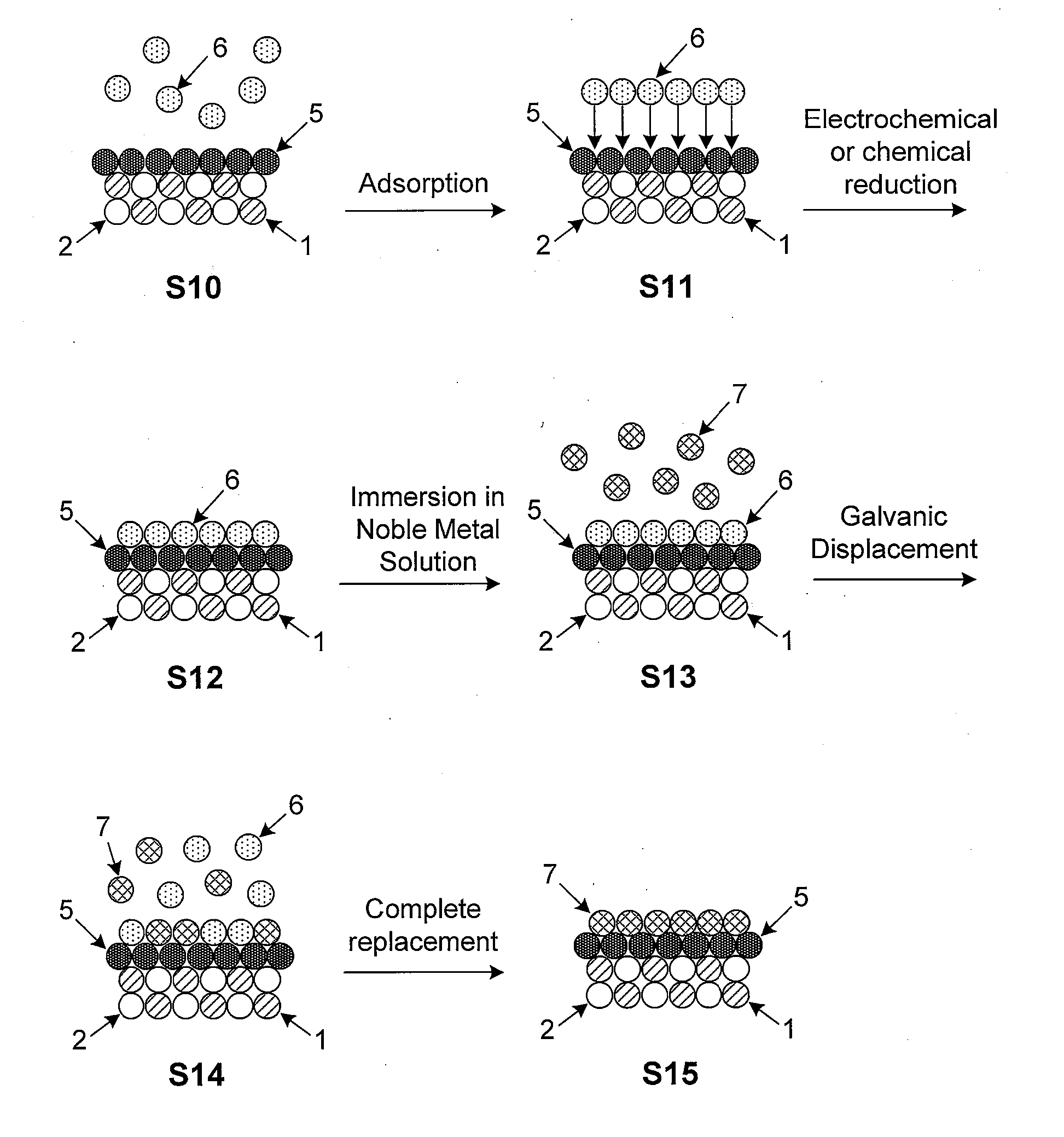
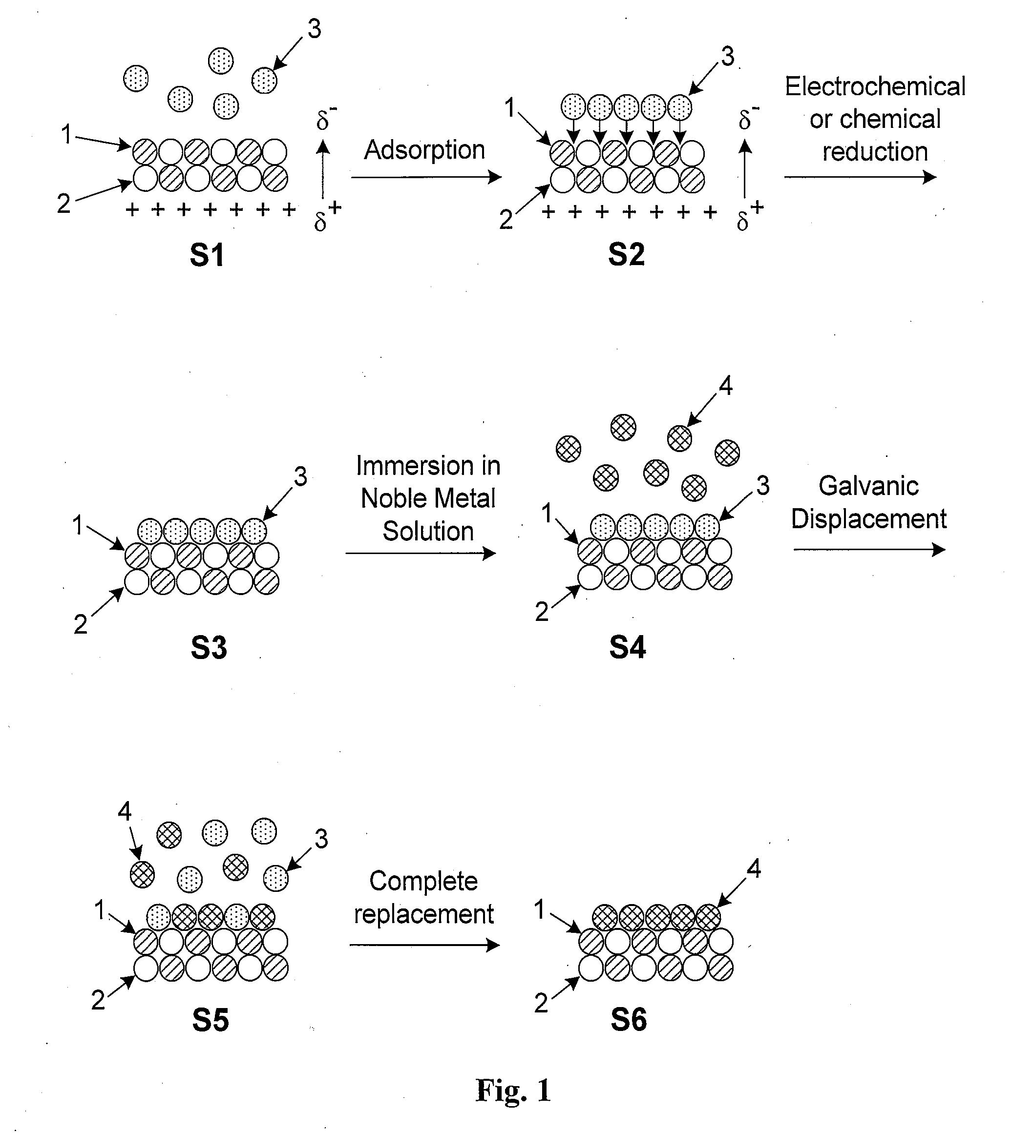
While batteries are capable of attaining high energy densities over a wide range of voltages, they cannot attain high power densities and can only undergo a limited number of recharge cycles.
Capacitors can provide high energy transfer rates with a nearly unlimited number of recharge cycles, but have limited charge storage capabilities.
However, its small pore size (typically a few nm in diameter) makes it difficult for ions in the electrolyte to access intrapore surfaces.
Furthermore, the use of insulating polymeric binders to fabricate the electrodes is detrimental to performance since it increases the resistance of the electrode.
However, access to inner wall surfaces of nanotubes is inhibited by the small diameter of the tube ends and its proportionally larger length.
The utilization of Ru is, however, inhibited by the high cost and scarcity of Ru as well as the toxicity of its oxides.
Controlled deposition of smooth, conformal thin films of Ru in the submonolayer to multilayer thickness range is also difficult to achieve.
A reduction to nanoscale dimensions yields a significant increase in the surface-to-volume ratio, thereby producing a concomitant increase in the surface area available for reaction.
Despite the performance improvements attainable with nanoscale electrocatalysts, successful commercialization of fuel cells requires still further increases in performance and cost efficiency.
Pt has been shown to be one of the best electrocatalysts, but its successful implementation in commercially available fuel cells is hindered by its extremely high cost, susceptibility to carbon monoxide (CO) poisoning, poor stability under cyclic loading, and the relatively slow kinetics of O2 reduction at the cathode.
Attempts to accelerate the oxygen reduction reaction (ORR) on Pt while simultaneously reducing Pt loading have been met with limited success.

Method used


Image

  • Platinum-Based Electrocatalysts Synthesized by Depositing Contiguous Adlayers on Carbon Nanostructures
  • Platinum-Based Electrocatalysts Synthesized by Depositing Contiguous Adlayers on Carbon Nanostructures
  • Platinum-Based Electrocatalysts Synthesized by Depositing Contiguous Adlayers on Carbon Nanostructures

Examples


Embodiment Construction

[0033]These and other objectives of the invention will become more apparent from the following description and illustrative embodiments which are described in detail with reference to the accompanying drawings. In the interest of clarity, in describing the present invention, the following terms and acronyms are defined as provided below.

ACRONYMS

[0034]ALD: Atomic Layer Deposition[0035]CVD: Chemical Vapor Deposition[0036]MBE: Molecular Beam Epitaxy[0037]ML: Monolayer[0038]MWNT: Multi-Walled NanoTube[0039]ORR: Oxidation Reduction Reaction[0040]PVD: Physical Vapor Deposition[0041]SWNT: Single-Walled NanoTube[0042]TEM: Transmission Electron Microscope[0043]UPD: Under Potential Deposition

DEFINITIONS

[0044]Adatom: An atom located on the surface of an underlying substrate.[0045]Adlayer: A layer of (atoms or molecules) adsorbed to the surface of a substrate.[0046]Bilayer: Two consecutive layers (of atoms or molecules) which occupy substantially all available surface sites on each layer and co...


PUM

PropertyMeasurementUnit
pressureaaaaaaaaaa
diameteraaaaaaaaaa
diameteraaaaaaaaaa

Abstract

High-surface-area carbon nanostructures coated with a smooth and conformal submonolayer-to-multilayer thin metal films and their method of manufacture are described. The preferred manufacturing process involves the initial oxidation of the carbon nanostructures followed by immersion in a solution with the desired pH to create negative surface dipoles. The nanostructures are subsequently immersed in an alkaline solution containing non-noble metal ions which adsorb at surface reaction sites. The metal ions are then reduced via chemical or electrical means and the nanostructures are exposed to a solution containing a salt of one or more noble metals which replace adsorbed non-noble surface metal atoms by galvanic displacement. Subsequent film growth may be performed via the initial quasi-underpotential deposition of a non-noble metal followed by immersion in a solution comprising a more noble metal. The resulting coated nanostructures may be used, for example, as high-performance electrodes in supercapacitors, batteries, or other electric storage devices.

Description

CROSS-REFERENCE TO RELATED APPLICATIONS[0001]This application claims priority under 35 U.S.C. §119(e) to U.S. Provisional Patent Appl. No. 61 / 155,178 which was filed on Feb. 25, 2009, and is a continuation-in-part of and claims priority under 35 U.S.C. §120 to co-pending U.S. patent application Ser. No. 12 / 603,216 which was filed on Oct. 21, 2009 and which, in turn, claims priority under 35 U.S.C. §119(e) to U.S. Provisional Patent Appl. No. 61 / 107,048 which was filed on Oct. 21, 2008, the entirety of all of which are incorporated by reference as if fully set forth in this specification.STATEMENT OF GOVERNMENT RIGHTS[0002]The present invention was made with Government support under contract number DE-AC02-98CH10886, awarded by the U.S. Department of Energy. The Government has certain rights in the invention.BACKGROUND[0003]I. Field of the Invention[0004]This invention relates generally to the field of nanoparticle electrocatalysts. In particular, the present invention relates to the...

Claims


Application Information

Patent Timeline
Patent Type & Authority Applications(United States)
IPC IPC(8): H01G9/058B01J23/56B05D5/12B05D3/06C23C16/26C25D5/54
CPCB82Y30/00B01J35/008C01B31/0293H01G11/36H01M4/92H01M4/926Y02E60/13Y02E60/50H01G11/24C23C28/02C23C28/321C23C28/322C23C28/34C23C28/345C23C28/347C23C28/42B01J23/56B01J37/348B01J35/0006B01J21/185B01J23/42B01J23/44B01J23/60B01J23/892B01J23/8926B01J35/0033B82Y40/00C01B32/18H01G11/04H01G11/28H01G11/58
Inventor ADZIC, RADOSLAVHARRIS, ALEXANDER
Owner BROOKHAVEN SCI ASSOCS
Why Eureka
Try Eureka