
Compact optical detection system

a detection system and optical technology, applied in the direction of optical radiation measurement, spectral modifiers, radiation measurement, etc., can solve the problems of high gain optical detectors, complex detectors, bulky or costly,

Inactive Publication Date: 2010-09-09
AGENCY FOR SCI TECH & RES
View PDF19 Cites 18 Cited by
  • Summary
  • Abstract
  • Description
  • Claims
  • Application Information

AI Technical Summary

Benefits of technology

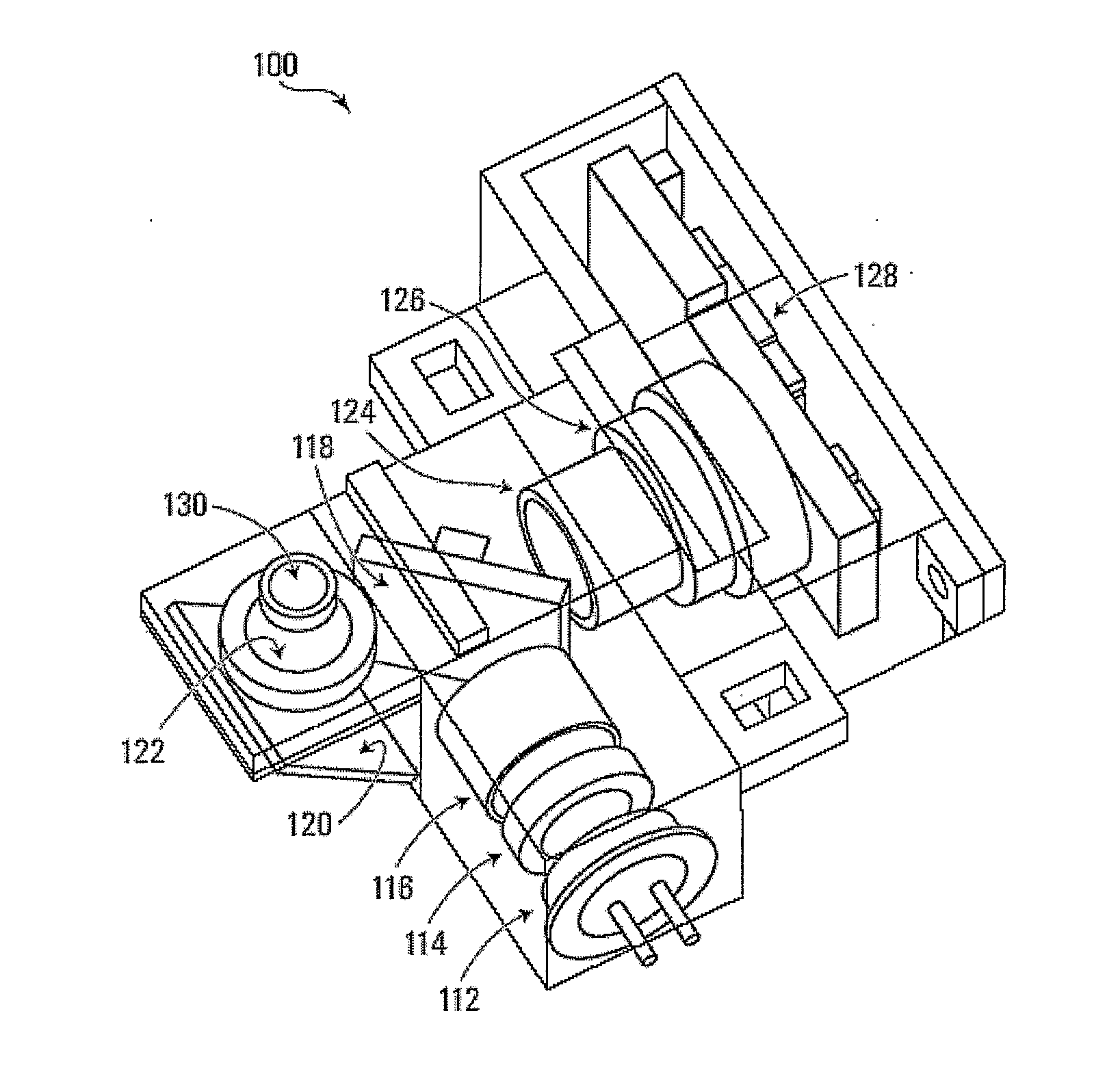
[0013]The detection system includes a conventional mirror, and the combination of the beam splitter and conventional mirror are used to reflect the excitation light beam and the emission light beam in such a manner that the light source and detector can be arranged within the same plane. Conveniently, the sample may be located in a different plane. For example, the detection system may be configured with the light source and the detector arranged substantially perpendicular to each other. Combination of the conventional mirror with a beam splitter, such as a dichroic mirror to direct the excitation and emission beams, and the resulting arrangement of light source and detector, results in a compact arrangement of the components of the detection system, making the detection system easily miniaturized and suitable for inclusion in hand-held lab-on-chip devices.

Problems solved by technology

However, as the entire un-directed fluorescence emission tends not to be fully received by the relatively small detectors typically incorporated in these devices, optical detectors with high gain tend to be required.
These detectors can be complex, bulky or costly and usually require special operating conditions, for example, operation in complete darkness or cooling.

Method used


Image

  • Compact optical detection system
  • Compact optical detection system
  • Compact optical detection system

Examples


example 1

[0085]A miniaturized fluorescence system with dimensions of 30 mm×30 mm×11 mm was designed and tested.

[0086]The properties of the detection system were determined by measuring a dilution series of the fluorescence dye fluorescein. The detection limit was found to be 1.96 nmol / L, which is more than sufficient for applications like real-time PCR.

[0087]The optical detection system has two sections: excitation and detection. The excitation section included a turquoise color LED model ETG-5CE490-15 (ETG Corp) as a light source. The LED has a peak emission wavelength of 490 nm with a luminous intensity of 6 cd (candela) and a viewing angle of 15°. Power losses were observed over the optical path, due to the viewing angle of the light source. Therefore, to collimate the light, the top of the LED plastic cover was cut by vertical milling 0.5 mm from the LED chip. The cut surface was then flattened with aluminum oxide abrasive waterproof paper and polished with a conventional diamond paste.

[...

example 2

[0107]A miniaturized economical real-time PCR made of micro-machined silicon was made, incorporating the above-described optical detection system.

[0108]Here, the compact, autonomous real-time RT-PCR device is described, having dimensions of 7 cm×7 cm×3 cm, with a weight of 75 g, or in a second embodiment, dimensions of 10 cm (diameter)×6 cm (height), with a weight of 150 g.

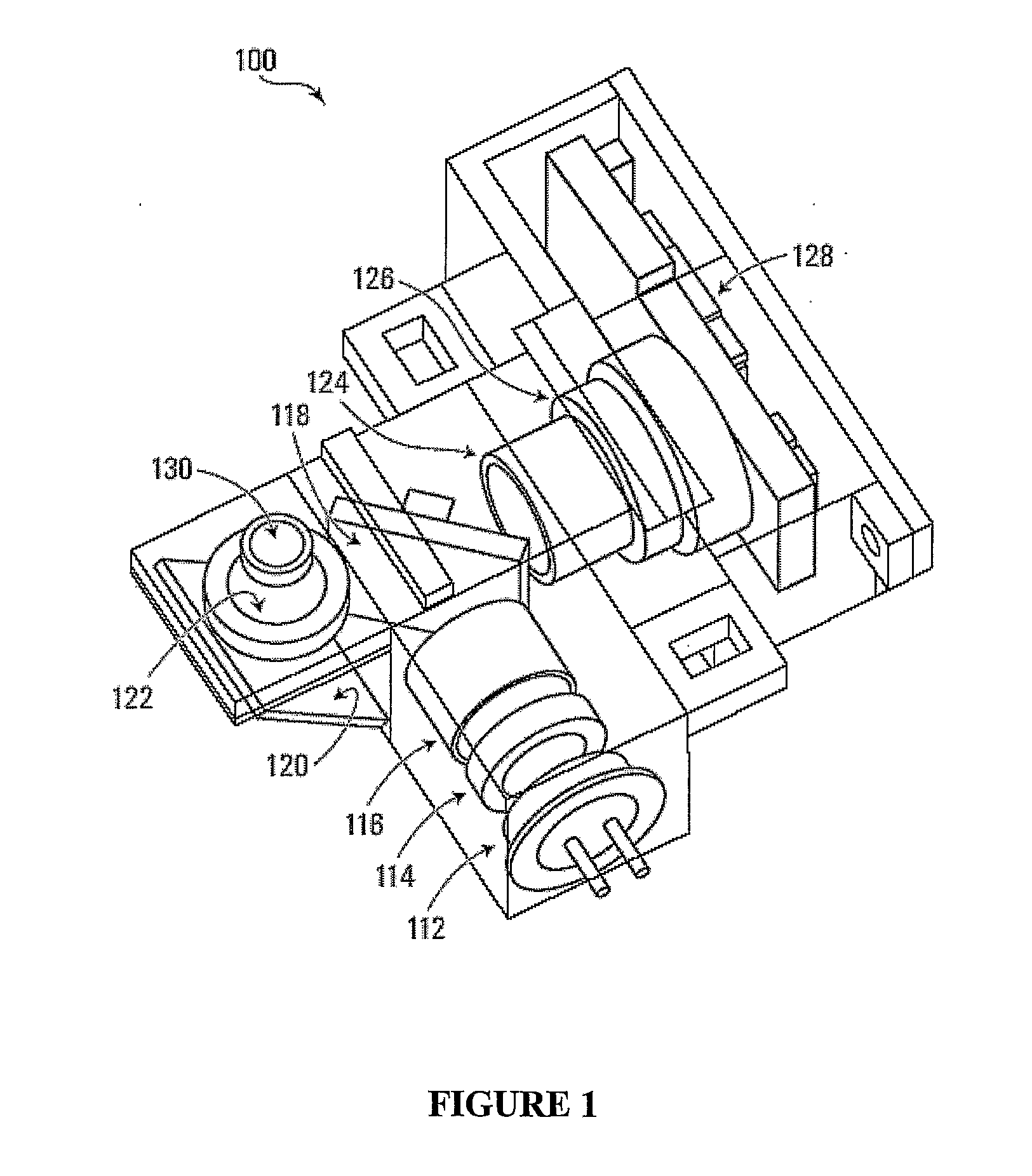
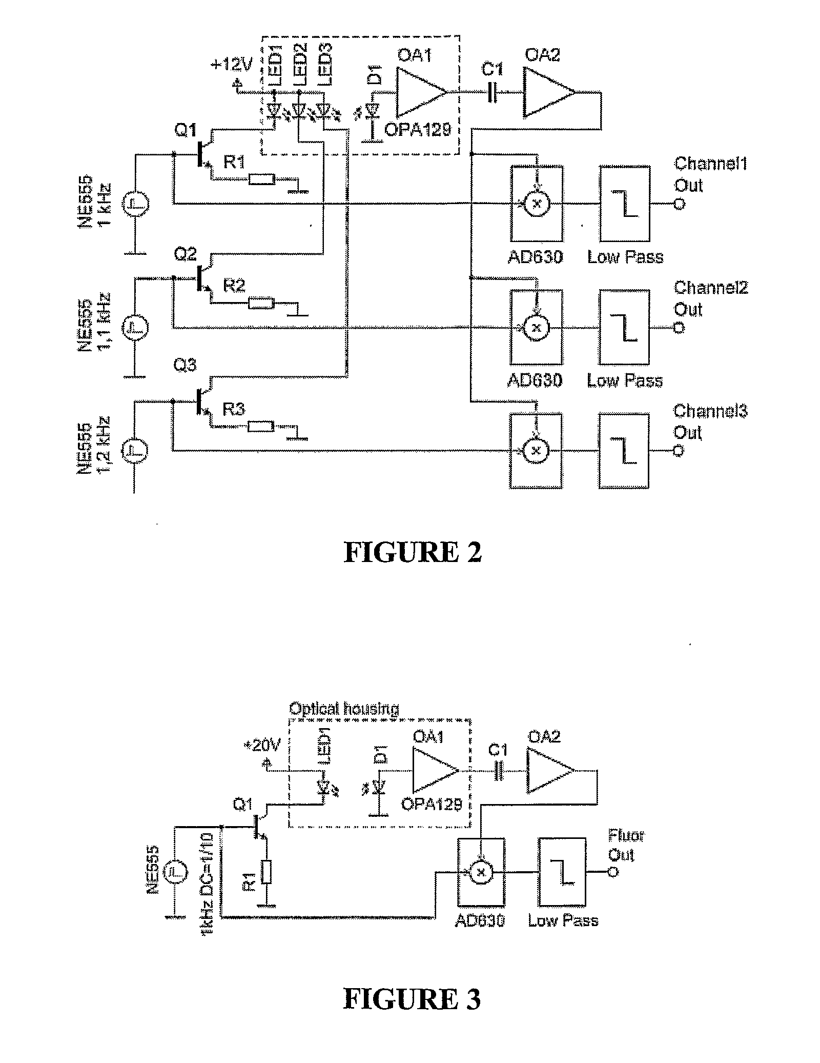
[0109]The PCR unit is integrated with a miniaturized fluorescence detection system and all the electronics necessary for the system's operation. The turquoise light emitting diode (490 nm peak excitation wavelength) is powered by current pulses with a peak amplitude of 100 mA. Photocurrent detected by a photodiode is processed by a lock-in amplifier making the optical system independent of ambient light.

[0110]A 12 Ah battery can be used to power the thermocycler device for up to 12 hours, as the consumption of the device is only 3 W. The compact size of the thermocycler device and its power consumption assure its ...

example 3

[0125]The portable thermocycler device was tested for the genetic analysis of an infectious disease. RT-PCR performance of the thermocycler device was demonstrated by detection of RNA isolated from the avian influenza virus (H5NI) using the RNA Master SYBR Green I RT-PCR Kit (Roche, Inc.) with PCR primers developed at the Institute of Molecular and Cell Biology of Singapore.

[0126]The reverse transcription was performed at 61° C. for 2 min and 30 s, followed by a hot start at 95° C. for 30 s. Amplification over 50 PCR cycles was carried out as follows: 3 s at 95° C. (denaturation), 15 s at 50° C. (annealing) and 20 s at 72° C. (extension). Once the PCR cycling was finished, melting curve analysis was conducted with a transition rate of 1° C. s−1. The total time necessary to detect the viral RNA was 14 min.

[0127]FIG. 11 shows the results of real-time RT-PCR using the present miniaturized thermocycler device to detect the H5N1 virus. The critical threshold for detection was found to be...


PUM

PropertyMeasurementUnit
peak excitation wavelengthaaaaaaaaaa
peak wavelengthaaaaaaaaaa

Abstract

A detection system is provided, the detection system comprising a light source that generates excitation light having a wavelength sufficient to excite a fluorophore in a sample; an excitation filter positioned along a first line along a path of the excitation light, the excitation filter transmitting the excitation light from the light source; a beam splitter positioned along the first line, the beam splitter reflecting the excitation light transmitted by the excitation filter along a second line toward a mirror positioned on one side of the beam splitter, and passing emitted light reflected along the second line; the mirror, positioned to reflect the excitation light from the beam splitter to the fluorophore in the sample along a third line, normal to both the first and second lines, wherein the mirror further reflects emitted light emitted along the third line, along the second line toward the beam splitter; an emission filter positioned along the second line, on a second side of the beam splitter; and a detector that detects the emitted light transmitted by the emission filter.

Description

CROSS-REFERENCE TO RELATED APPLICATION[0001]This application claims the benefit of, and priority from, U.S. provisional patent application No. 60 / 839,678, filed on Aug. 24, 2006, the contents of which are incorporated herein by reference.FIELD OF THE INVENTION[0002]The present invention relates generally to optical detection systems, and particularly to compact optical detection systems for detection of a fluorescent signal.BACKGROUND OF THE INVENTION[0003]Lab-on-a-chip systems have been developed for various applications, such as drug discovery, pathogen detection, and others. These systems process biological or chemical samples, and provide for qualitative or quantitative detection of a target molecule or particle. Such systems use miniaturized components and are designed to be portable, allowing for sample testing in the field.[0004]Particularly, the necessity for portable devices capable of field use to detect biological weapons, pathogens or viruses has resulted in the developm...

Claims


Application Information

Patent Timeline
Patent Type & Authority Applications(United States)
IPC IPC(8): C12M1/34G01J1/58
CPCB01L3/5088G01N2201/0693B01L2200/147B01L2300/1827G01N21/0332G01N21/6428G01N21/645G01N21/76G01N21/763G01N2021/6419G01N2021/6421G01N2021/6441G01N2201/0221G01N2201/0625G01N2201/0627B01L7/52
Inventor NEUZIL, PAVELPIPPER, JUERGENNOVAK, LUKAS
Owner AGENCY FOR SCI TECH & RES
Learn More