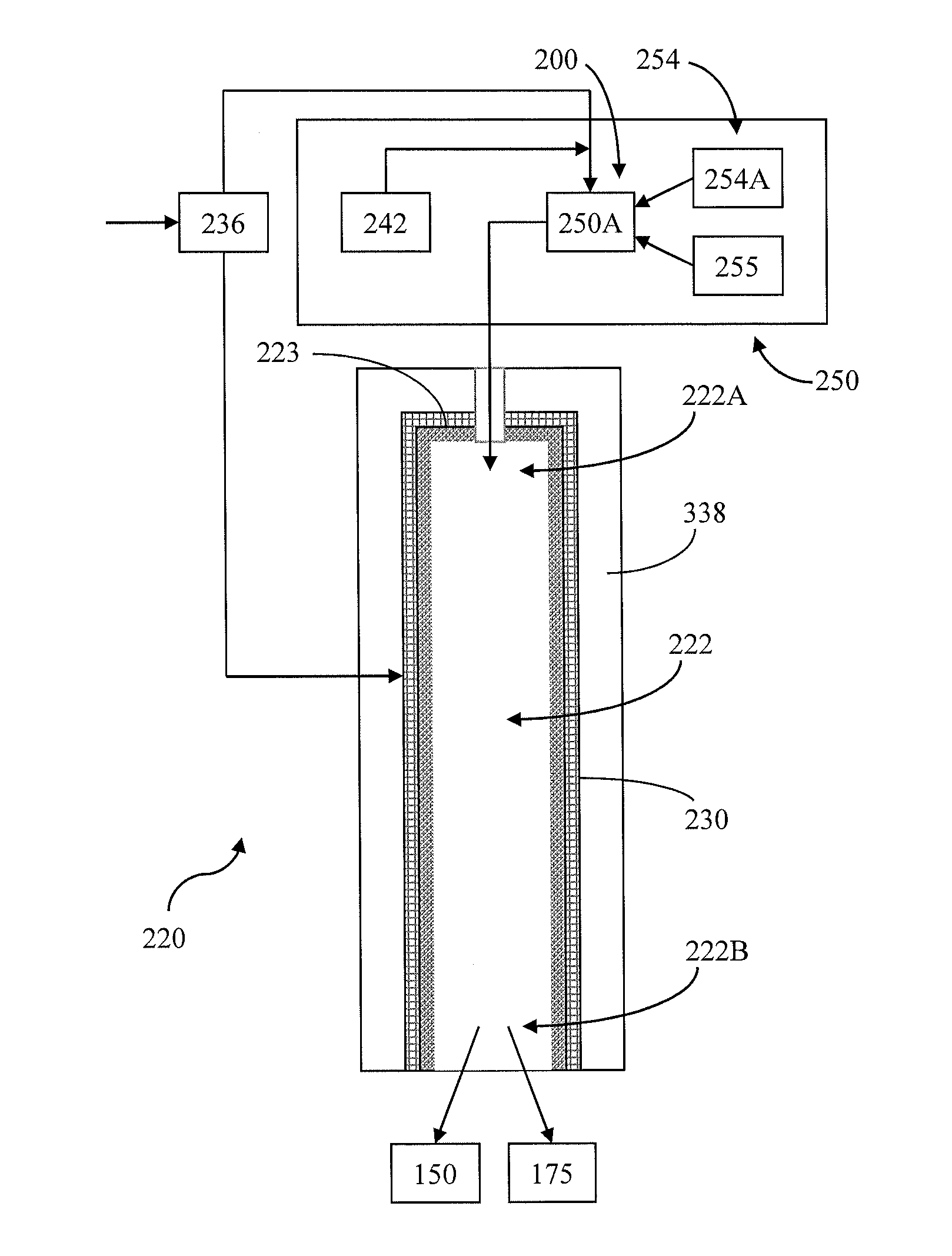
[0009]In another aspect, the present disclosure provides a combustion method, initially comprising mixing a carbonaceous fuel with enriched oxygen and a working fluid using a mixing arrangement to form a fuel mixture. The fuel mixture is received in an inlet portion of a
combustion chamber defined by a transpiration member, wherein the transpiration member is at least partially surrounded by a pressure containment member. The fuel mixture is combusted within the combustion chamber at a combustion temperature to form a combustion product, and the combustion product then directed toward an outlet portion of the combustion chamber. A transpiration substance is directed through the transpiration member toward the combustion chamber such that the transpiration substance buffers interaction between the combustion product and the transpiration member. In addition, the transpiration substance may be introduced into the combustion chamber to achieve a desired outlet temperature of the combustion product.
[0012]In another aspect, oxy-fuel combustion of carbonaceous fuels (and / or hydro-carbonaceous fuels) may also involve the separation of substantially
pure oxygen from air (or otherwise providing such substantially
pure oxygen) and its use as in the
combustion process to produce
combustion products which are substantially free of
nitrogen and which comprise
carbon dioxide and
water vapor. The carbon dioxide-rich combustion product (following cooling and water condensation) may then be available for subsequent commercial use, such as for
enhanced oil recovery or enhanced
natural gas production or disposal in a suitable
geological sequestration site (following compression and purification). Operation of an oxy-fuel power production
system at
high pressure may also allow the carbon dioxide derived from the fuel to be produced at a high pressure, resulting in power savings by reducing or eliminating the need to pressurize the carbon dioxide. Further, high pressure operation may allow the purified
combustion products to be used directly in a
power cycle, when mixed with a suitable heated working fluid such as CO2 or steam. The operation of the power
system at high pressure may also lead to reduced volumetric fluid flow rates in the
power cycle, resulting in smaller equipment and lower capital costs. The high pressure oxy-fuel
combustor with provision for
temperature control is another important aspect.
Cycling of a suitable fluid such as combustion
product gas or carbon dioxide or
liquid water or steam (such as from a recycle
stream) through a transpiration-cooled and protected wall of the combustion chamber / space may also serve to control the combustion temperature. Flow of the transpiration fluid through the combustion chamber walls may also serve to eliminate damage to and / or build-up on the chamber walls due to heat, or ash or
liquid slag impingement effects. Thus, an efficient high pressure, high temperature combustor is provided which can be adapted to burn a variety of gaseous, liquid, or
solid fuels or fuel mixtures to meet various requirements as part of a power
system which can operate at significantly higher efficiencies and lower capital costs than present technology. In some instances, the combustor may be operated to produce a combustion product comprising
hydrogen and
carbon monoxide to be made available to downstream requirements, other than power production.
[0013]In still a further aspect, the present disclosure generally provides methods and apparatuses associated with a high pressure, high temperature, high efficiency, transpiring fluid-protected, oxy-fuel combustor for use, for example, in power generation, such as in combination with a
power cycle using either CO2 and / or H2O as a working fluid. In such an application, the combustor can be operated in an oxidizing mode, whereby the combustion products produced thereby contain an oxygen concentration in the range of between about 500 ppm and about 3%
molar, and a
carbon monoxide concentration below about 50 ppm, preferably below about 10 ppm
molar. In another aspect, the combustor can be operated in a reducing mode whereby the combustion products produced thereby have near zero oxygen concentration and the combustion products contain a concentration of CO and H2, Operation in the reducing mode can be configured to maximize the production of H2 and CO, and to minimize the consumption of O2 The reducing mode of operation may be beneficial not only for power production, but also for production of H2 or H2+CO synthesis gas. In particular aspects, the operating pressure may be in the range of between about 40 bar and about 500 bar, and preferably at least 80 bar, and the combustion product temperature may be generally in the range of between about 1300° C. and about 3500° C.
[0014]In aspects involving power production, a portion of a working fluid is introduced into the combustor, along with the fuel and oxidant (i.e., enriched oxygen), for combustion, such that a high pressure, high temperature fluid
stream (combustion product) is produced comprising the working fluid and the combustion products. The working fluid can be introduced through the transpiration-protected walls of the combustion chamber and / or through additional injection points about the combustion chamber. The working fluid, following the combustion process and mixing with the combustion products through transpiration, may have a temperature in a range suitable (i.e., low enough) for introduction directly into a power generation device, such as a
turbine. In such instances, the total quantity of working fluid introduced into the combustor, as a
diluent to the combustion products, may be adjusted to provide an exit temperature for the total working fluid
stream leaving the combustor which is suitable for the operating
inlet temperature and pressure of the
power turbine. Advantageously, the fluid stream may be maintained at a relatively high pressure during expansion in the
turbine such that the pressure ratio across the
turbine (i.e., the ratio of the pressure at the inlet to the pressure at the outlet of the turbine) is less than about 12. The fluid stream can also be further processed to separate the components of the fluid stream, wherein such
processing can include passing the fluid stream through a
heat exchanger. In particular, the expanded working fluid (at least a portion of which may be recycled from the fluid stream) can be passed through the same
heat exchanger to heat the high pressure working fluid prior to introduction of the same into the combustor. In certain aspects, the disclosure provides a high pressure oxy-fuel combustor for power production systems that can produce power at high efficiency with low
capital cost and also can produce substantially pure CO2 at pipeline pressure for commercial use or sequestration. The CO2 also may be recycled into the power production system.
[0017]In still another aspect, the present disclosure may provide the ability to reduce the physical size and
capital cost of a
power generation system compared to current technologies using a similar fuel. Thus, the methods and systems of the present disclosure can contribute to or otherwise facilitate significantly reduced construction costs associated with power production systems, and the relatively high efficiency of certain system combinations can lead to reduced costs of
electricity or energy production, as well as reduced use of fossil fuels.

