System and method for communicating with an implant

a technology for implant communication and implants, applied in the field of orthopaedic implants, can solve the problems of increased risk to the health of patients, insufficient diagnosis of x-rays, and inability to accurately diagnose, etc., and achieve the effect of high permeable material and stable reading

Inactive Publication Date: 2011-01-06
SMITH & NEPHEW INC
View PDF110 Cites 158 Cited by
  • Summary
  • Abstract
  • Description
  • Claims
  • Application Information

AI Technical Summary

Benefits of technology

[0029]The invention includes a system having a telemetric implant. The telemetric implant is capable of receiving power wirelessly from an external reader at a distance using sophisticated digital electronics, on board software, and radio frequency signal filtering. The implant may be equipped with at least one sensor, interface circuitry, micro-controller, wakeup circuit, high powered transistors, printed circuit board, data transmitter and power receive coil with software algorithm, all of which may be embedded in machined cavities located on the implant. The telemetry system may use a coiled ferrite antenna housed and protected inside the metallic body of the implant using a metal encapsulation technique suitable for long term implantation. The use of digital electronics and a high permeable material located inside a metallic cavity compensates for the effect of severely shielding a power coil from the externally applied magnetic power field. The digital electronics enables multiplexing to read multiple sensors. The electronics module does not require the reader to be positioned within a pre-defined “sweet spot” over the implant in order to achieve a stable reading relating to sensed data minimizing the potential to collect erroneous measurements.

Problems solved by technology

In some instances, however, improper installation, implant failure, infection or other conditions, such as patient non-compliance with prescribed post-operative treatment, may contribute to compromised healing of the fracture, as well as increased risk to the health of the patient.
However, x-rays may be inadequate for accurate diagnoses.
They are costly, and repeated x-rays may be detrimental to the patient's and health care workers' health.
In some cases, non-unions of fractures may go clinically undetected until implant failure.
Moreover, x-rays may not be used to adequately diagnose soft tissue conditions or stress on the implant.
Current methods of assessing the healing process, for example using radiography or patient testimonial do not provide physicians with sufficient information to adequately assess the progress of healing, particularly in the early stages of healing.
X-ray images only show callus geometry and cannot access the mechanical properties of the consolidating bone.
Therefore, it is impossible to quantify the load sharing between implant and bone during fracture healing from standard radiographs, CT, or MRI scans.
Unfortunately, there is no in vivo data available quantifying the skeletal loads encountered during fracture healing as well as during different patient and physiotherapy activities.
Many times the caregiver does not know the status of a would-be or existing patient and, therefore, may only be able to provide information or incite after it was necessary.
Surgeons have historically found it difficult to assess the patient's bone healing status during follow up clinic visits.
However, skepticism of the risks associated with wireless power and communication systems has prevented widespread adoption, particularly in orthopaedic applications.
Today's medical devices face an increasingly demanding and competitive market.
Although data transmission ranges in excess of 30 m have been observed previously, energy coupling ranges are typically reduced to a couple of inches using wireless magnetic induction making these implants unsuitable for commercial application.
However, a re-implantation procedure must be performed when the battery is exhausted, and a patient obviously would prefer not to undergo such a procedure if possible.
In general, these items must be hermetically sealed to a high standard because many electronic components contain toxic compounds, some electronic components need to be protected from moisture, and ferrite components, such as the antenna, may be corroded by bodily fluids, potentially leading to local toxicity issues.
Many polymers are sufficiently biocompatible for long-term implantation but are not sufficiently impermeable and cannot be used as encapsulants or sealing agents.
Additionally, surgeons have found it difficult to manage patient information.

Method used


Image

  • System and method for communicating with an implant
  • System and method for communicating with an implant
  • System and method for communicating with an implant

Examples


first embodiment

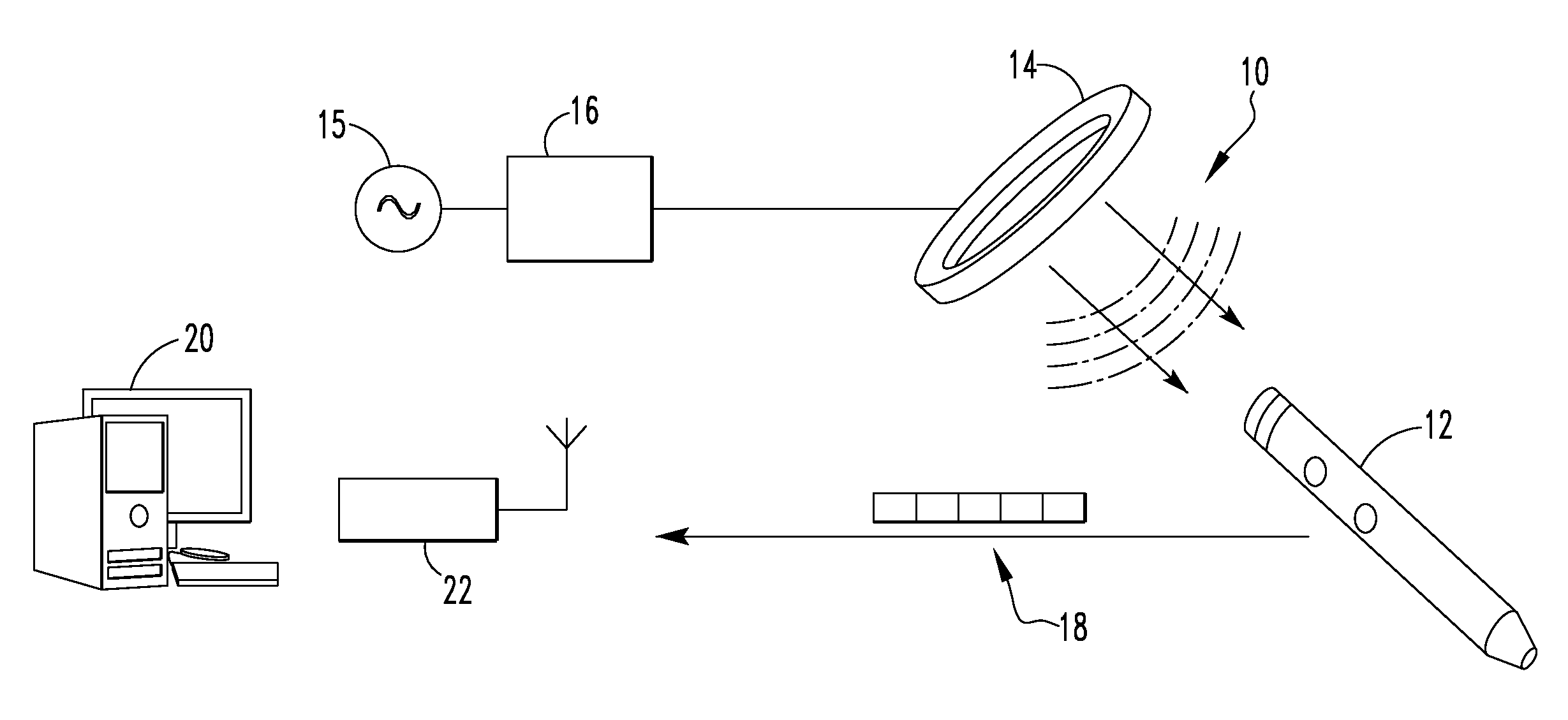
[0056]FIG. 1 illustrates a system 10 for communicating with an implant in a The system 10 includes an orthopaedic implant 12, a coil 14, a signal generator 15, an amplifier 16, a data packet 18, a processor 20, and a receiver 22. In the depicted embodiment, the orthopaedic implant is an intramedullary nail but other types of orthopaedic implants may equally be used. As examples, the orthopaedic implant may be an intramedullary nail, a bone plate, a hip prosthetic, or a knee prosthetic. Further, the processor 20 is depicted as a desktop computer in FIG. 1 but other types of computing devices may equally be used. As examples, the processor 20 may be a desktop computer, a laptop computer, a personal data assistant (PDA), mobile handheld device, or a dedicated device. In some embodiments, the processor 20 and the receiver 22 form a single component. In the depicted embodiment, however, the receiver 22 is electrically connected to the processor 20 but is a separate component. As example...

second embodiment

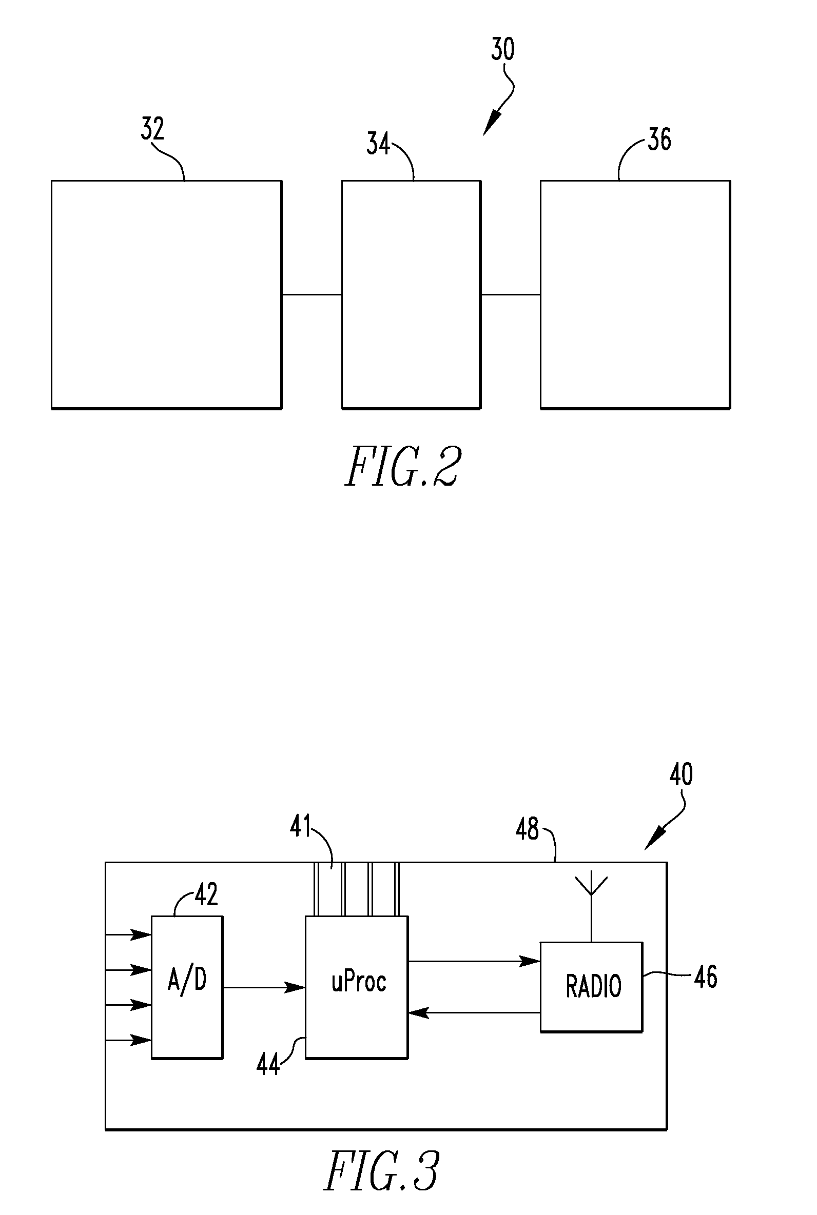
[0067]FIG. 10 schematically illustrates on-board implant electronics 80. In FIG. 10, some components, such as a power supply, have been removed for clarity. The on-board implant electronics 80 includes a plurality of sensor and wheatstone bridge assemblies 82, a multiplexer 83, an amplifier 84, a microprocessor 86, and a transmitter 88. In its simplest form, the multiplexer 83 is an addressable switch. The multiplexer 83 is linked to the microprocessor and selects the sensor from which to receive data. In the depicted embodiment, the sensor assembly 82 includes a foil gauge connected to a wheatstone bridge. Alternatively, the sensor may be a semiconductor strain gauge. The microprocessor 86 includes an analog-to-digital converter that converts the analog signal from the sensor assembly to a digital signal. When the sensor assemblies 82 are powered, each sensor assembly 82 sends a signal to the multiplexer 83. The multiplexer 83 sends the multiplexed signal to the amplifier 84, which...

third embodiment

[0076]FIG. 26 illustrates a system 310 for communicating with an implant in a The system 310 includes an orthopaedic implant 312, a paddle 314, a data packet 318, a first processor 320, and a control unit 322. In the depicted embodiment, the orthopaedic implant 312 is an intramedullary nail but other types of orthopaedic implants may equally be used. As examples, the orthopaedic implant 312 may be an intramedullary nail, a bone plate, a hip prosthetic, or a knee prosthetic. Further, the first processor 320 may be a desktop computer, a laptop computer, a personal data assistant (PDA), mobile handheld device, or a dedicated device. In some embodiments, the first processor 320 and the control unit 322 form a single component. In the depicted embodiment, however, the control unit 322 is electrically connected to the processor 320 but is a separate component. Optionally, the system 310 also may include a feedback indicator 324, a load scale 326, a portable storage device 328, and / or a s...


PUM


Abstract

A system and method for communicating with a medical implant is disclosed. The system (10,210,310,410) includes on-board electronics, a signal generator (15,215), an amplifier (16,216), a coil (14,214), a receiver (22,222), and a processor (20,220). The on-board electronics (100, 110) include a power harvester, a sensor, a microprocessor, and a data transmitter. The signal generator (15,215) generates a first signal, the amplifier (16,216) amplifies the first signal, the coil (14,214) transmits the amplified signal, the power harvester receives the first signal and transmits a data packet (18,218) containing data, the receiver (22,222) receives the data packet (18,218), and the processor (20,220) either processes the data or sends the data to a data storage device.

Description

CROSS-REFERENCE TO RELATED APPLICATIONS[0001]This application claims the benefit of U.S. Provisional Application No. 61 / 025,362, filed on Feb. 1, 2008 and U.S. Provisional Application No. 61 / 044,295, filed on Apr. 11, 2008. The disclosure of each prior application is incorporated by reference in its entirety.BACKGROUND OF THE INVENTION[0002]1. Field of the Invention[0003]The present invention relates generally to orthopaedic implants and more particularly to orthopaedic implants that incorporate a portion of a radio telemetry system.[0004]2. Related Art[0005]Trauma products, such as intramedullary (IM) nails, pins, rods, screws, plates and staples, have been used for many years in the field of orthopaedics for the repair of broken bones. These devices function well in most instances, and fracture healing occurs more predictably than if no implant is used. In some instances, however, improper installation, implant failure, infection or other conditions, such as patient non-compliance...

Claims


Application Information

Patent Timeline
Patent Type & Authority Applications(United States)
IPC IPC(8): A61B5/07H04B5/00
CPCA61B5/0031A61B5/076H01Q7/00A61F2250/0002H01Q1/02A61B5/4504A61B5/6878
Inventor JANNA, SIED W.WILSON, DARREN JAMESFELL, ANDREW JONTEGERDINE, DAVID ROGERGRAHAM, ABI CLAIRETAYLOR, STEPHEN RUSSELL
Owner SMITH & NEPHEW INC
Why Eureka
Try Eureka