Automotive adsorption heat pump

a heat pump and auto-adsorption technology, applied in the field of auto-adsorption heat pumps, can solve the problems of long delay (5+ min.) in the frigid period, attendant losses in efficiency, and cannot meet the efficiency of the best reversed rankine cycle design, and achieve the effect of less expensive and efficient and reliabl

Inactive Publication Date: 2011-01-13
LAMBERT MICHAEL A +1
View PDF6 Cites 44 Cited by
  • Summary
  • Abstract
  • Description
  • Claims
  • Application Information

AI Technical Summary

Benefits of technology

[0037]It is an object of the present invention to provide a new and enhanced adsorption heat pump which is more efficient and reliable, as well as less expensive.

Problems solved by technology

Although China and India have the #1 and #2 populations (⅓ of the world's) and are rapidly developing, consuming ever greater amounts of oil, reliable inexpensive transportation is still the order of the day, so air conditioning automobiles is not yet a significant consideration.
The only drawback is the long delay (5+ min.) during frigid weather between engine start-up and effective cabin heating and defrosting.
The fuel pump runs constantly, but the thermostatically controlled radiator fan often shuts off at city cruise speed.
There are a number of thermal effect devices which can convert wasted exhaust heat directly into cabin cooling without having to go through the intermediate step of producing electricity with the attendant losses in efficiency.
Recent improvements in efficiency of reversed Stirling cycle systems (achieving COPC=3.0) still do not approach the efficiency of the best reversed Rankine cycle designs (COPC≧5).
But it cannot be belt driven by the engine if the goal is to eliminate the parasitic power loss associated with cabin cooling.
This combination of three components would add considerable mass.
Each energy transformation from heat to electricity to mechanical work to heat (cooling) would incur loss in efficiency.
But, even ignoring this degradation of performance, a reversed Stirling cycle heat pump capable of delivering 7 kW of cooling would have a mass of 580 kg [=7000 W=12 W.kg−1], not accounting for the considerable mass of the thermo-electric generator.
“Double effect” heating or “heat recovery” (i.e., recycling of heat) yields up to COPC=1.2, but such devices are bulkier, more complex, and costlier.
They had difficulties in designing major components to meet geometrical and functional specifications for integration in a car.
High system mass was also a problem.
Separation of the refrigerant from the absorbent in the “generator” was strongly affected by acceleration and vibration.
They suggested that the best refrigerant-absorbent pair was H2O—LiBr, but cautioned that corrosion by the hot brine was a challenging problem.
The other three alternate cooling technologies are either unfeasible or not as promising as solid-vapor adsorption cooling for reasons described above.
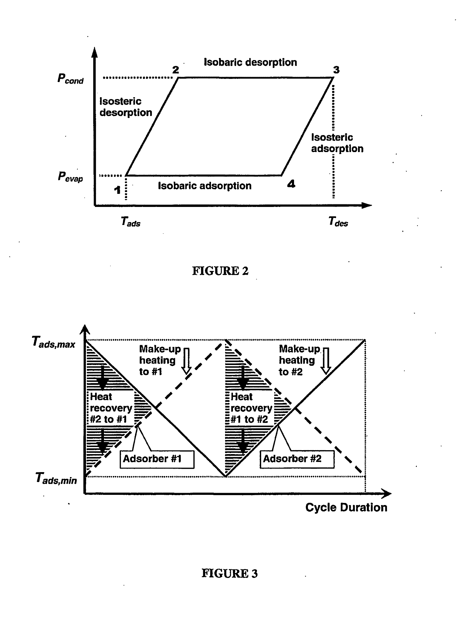
Once the beds reach equal temperature, double effect heating is no longer possible (FIG. 3).
Thus, the theoretical limit of heat recovery for a two-bed device is 50%, but the aforementioned 40% is the practical limit [9].
According to Lambert and Jones [16], some designs suffer from low thermal mass ratio Cads / Cinert, the first of the two critical governing parameters identified above.
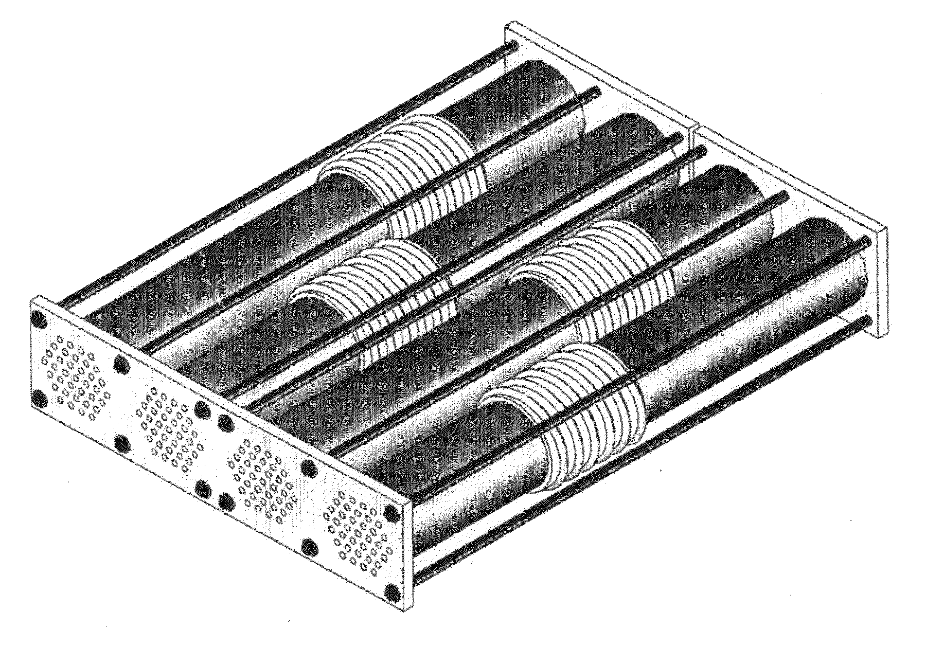
And most also suffer from low NTU, the second critical governing parameter, because they do not distribute heat effectively due to small contact area Acontact between the HEX and a given volume of adsorbent ads, such as the concentric tube configurations in FIGS. 5 and 6.
However, this design posed insurmountable problems in manufacturability, reliability, and expense, owing to its delicate configuration and sub-atmospheric pressure that allowed for air leaks into the system.
Another limitation of previous designs is that none embody a satisfactory method for increasing the poor thermal conductivity of adsorbents kads while retaining sufficient permeability to refrigerant vapor.
Some designs use a coiled tubing HEX inside beds of packed spheres [17], resulting in a very low effective kads.
None of the studies consider settling of the adsorbent particles, which may cause adsorbent to lose contact with the heat exchanger.

Method used


Image

  • Automotive adsorption heat pump
  • Automotive adsorption heat pump
  • Automotive adsorption heat pump

Examples


Embodiment Construction

[0092]As used in this disclosure, the singular forms “a”, “an”, and “the” may refer to plural articles unless specifically stated otherwise. Furthermore, the use of grammatical equivalents of articles is not meant to imply differences among these terms unless specifically indicated in the context. Unless defined otherwise, all technical and scientific terms used herein generally have the same meaning as commonly understood by one of ordinary skill in the art to which this invention belongs.

[0093]To facilitate understanding of the invention set forth in the disclosure that follows, a number of terms are defined below.

Nomenclature

[0094]A surface, contact, or cross-sectional area (m2)[0095]cp specific heat (J.kg−1.K−1)[0096]C thermal capacitance, or thermal “mass,” C=m×cp (J.K−1)[0097]C• dynamic thermal capacitance, C•=m•×cp (W.K−1)[0098]COPC coefficient of performance for cooling, a dimensionless measure of efficiency[0099]Dh hydraulic diameter (m)[0100]hads heat of adsorption (kJ.kg−...


PUM


Abstract

An adsorber unit has an outer shell, a plurality of internal tubes extending through the shell for carrying heat transfer fluid, each tube having outwardly projecting fins along its entire length, and a solid adsorbent material in the shell surrounding the tubes such that the fins project into the adsorbent material, the fins being of a material (e.g., metal) of higher thermal conductivity than the adsorbent material. Metal wool loosely packed inside the tubes, or internal radial fins swaged into the tubes, increase internal surface area thereby enhancing convective heat transfer. Metal wool loosely packed between the external fins, or fine wire metal coils lightly squeezed between the external fins, further increase external surface area of the heat exchanger in contact with the adsorbent thereby enhancing contact heat transfer. Performance is enhanced because the external fins and wool or wire coils transport heat more efficiently to all regions of the adsorbent, and permit less non-adsorbent heat exchanger material (e.g., metal) to be used for a given amount of adsorbent. Two or more such units are used in an adsorption heat pump. This design utilizes existing components (e.g., shell-&-tube heat exchanger, internally and externally finned tubing, and metal wool or wire coils) in a novel manner heretofore untried. In one exemplary embodiment, automobile air conditioning, exhaust heat is used to power such an air conditioner. The significant additional power used by the mechanical compressor of an automobile (12%-17% during commuting for subcompact to midsize cars) can be nearly eliminated by powering the air conditioner with otherwise wasted exhaust heat. The adsorbent is heated and cooled by light oil (called Heat Transfer Fluid, HTF) which in turn is heated and cooled by exhaust and fresh air. Such indirect heating and cooling achieves the required efficiency, and allows using phase change material (e.g., wax) to store and therefore fully utilize exhaust heat. A refrigerant reservoir is included which provides immediate cooling after start-up of a cold engine, while the exhaust system and heat pump are still heating up in order to start pumping refrigerant. Eliminating the mechanical compressor increases fuel mileage by 14-18% for midsize, compact, MS and subcompact cars, or 4.6-6.0% annually, given a four-month cooling season.

Description

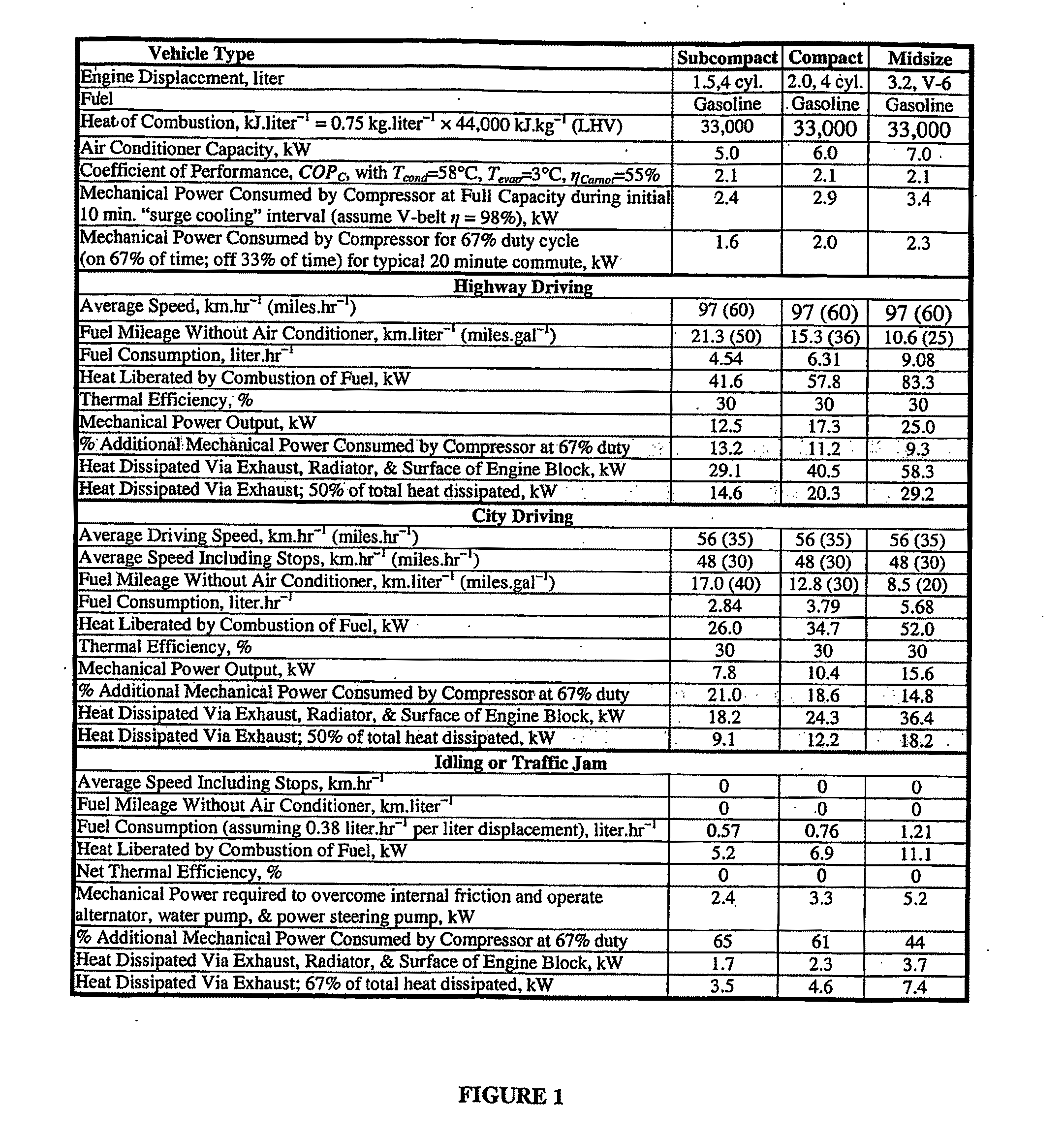
CROSS REFERENCE TO RELATED APPLICATION[0001]This application claims the benefit of U.S. Provisional Application No. 60 / 689,664, filed Jun. 10, 2005.BACKGROUND OF THE INVENTION1. Automotive Cooling Technology Options1.1 Typical Driving Scenario[0002]In order to estimate the fuel savings afforded by an adsorption air conditioner, it is necessary to define the basis of the estimation, which will be the typical commute to and from work. In the USA, driving mileage is distributed 38% commuting, 35% for running family businesses, and 27% for social, recreational, and religious activities. The average yearly mileage has increased from 16,539 km in 1990 to 18,870 km in 1999 [1], so a round estimate of 19,312 km.yr−1 (12,000 miles.yr−1) is assumed for 2006. Therefore, the average round trip commute is 30.6 km=(19,312 km.yr−1×38% commuting÷240 work days).[0003]Assuming the typical commute is 50% city driving and 50% highway driving, and that the average city street speed is 56 km.hr−1 (35 mil...

Claims


Application Information

Patent Timeline
Patent Type & Authority Applications(United States)
IPC IPC(8): F25B15/00
CPCB60H1/32F25B27/02F25B17/083B60H1/3201Y02A30/274B60H1/32014
Inventor LAMBERT, MICHAEL A.JONES, BENJAMIN J.
Owner LAMBERT MICHAEL A
Why Eureka
Try Eureka