Corrosion reduction system for power generation plants during shutdown

a power generation plant and shutdown technology, applied in the direction of corrosion diminishing boiler components, specific water treatment objectives, water/sludge/sewage treatment, etc., can solve the problems of overheating tube failure, hydrogen damage, and under deposit corrosion attack, so as to reduce or eliminate internal contamination. , the effect of reducing the corrosion

Inactive Publication Date: 2011-03-24
STODOLA JAN
View PDF0 Cites 6 Cited by
  • Summary
  • Abstract
  • Description
  • Claims
  • Application Information

AI Technical Summary

Benefits of technology

[0016]The object of this invention is a reduction of corrosion inside power generation cycle equipment during plant shutdown and start-up periods by substantially reducing or totally eliminating internal contamination with corrosion causing ac

Problems solved by technology

During power plant shutdown periods, some or all parts of the power generating cycle are opened to atmosphere and the quality of water in contact with internal cycle surfaces is typically well outside the recommended control range proportionately increasing system corrosion.
In boilers, reduction of heat transfer due to deposits may lead to overheating tube failures or, if corrosive anions are also present, to under deposit corrosion attack, such as hydrogen damage.
Deposits in turbines may lead both to corrosion failures due to under-deposit corrosion attack and/or plant capacity reduction.
It is also known that low pH water during plant start-ups and shut downs causes initiation and/or propagation of corrosion fatigue cracks on internal surfaces of thermally stressed carbon steel plant components.
Corrosion fatigue failures in boilers are known to be the main cause of plant unreliability but similar type failures in de-aerators and turbines are also important since they may be catastrophic, causing long periods of plant unavailability (EPRI, Palo Alto, Calif., TR-106696, November 1997).
Deposition of corrosion products in nuclear power plant cycles is also known to aggravate health and safety problems due to increased radioactive radiation exposure of station staff.
Further, the necessary periodic removal of excessive levels of corrosion products with chemical

Method used


Image

  • Corrosion reduction system for power generation plants during shutdown
  • Corrosion reduction system for power generation plants during shutdown
  • Corrosion reduction system for power generation plants during shutdown

Examples


Embodiment Construction

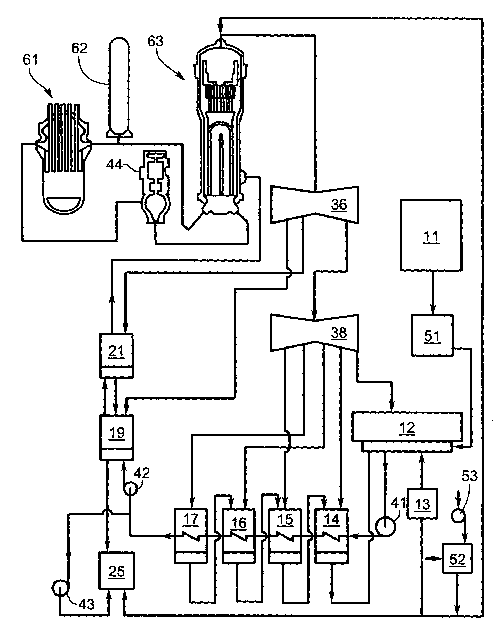
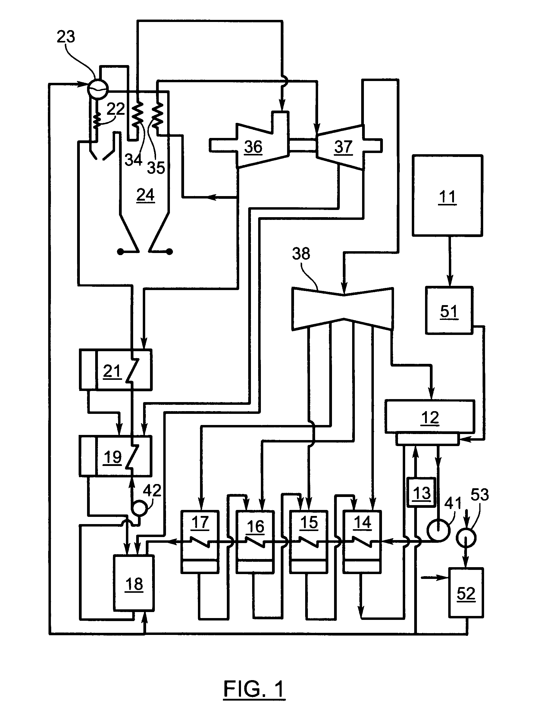
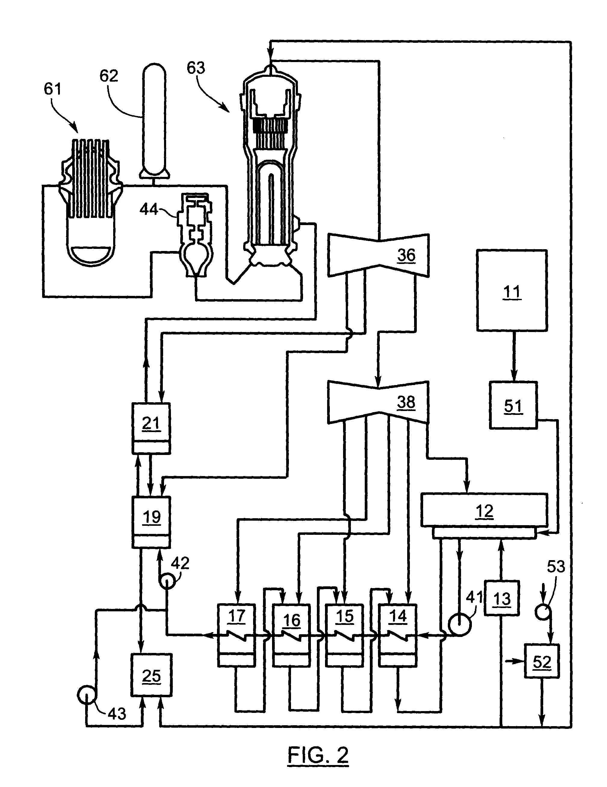
[0024]In order to more clearly understand the present invention part numbers as assigned in the following parts list will be used:

Part NumberDescription11make-up water (condensate) storage12main steam condenser13vacuum breaker14low pressure heater15low pressure heater16low pressure heater17low pressure heater18de-aerating heater19high pressure heater21high pressure heater22economizer23steam drum24boiler25drain tank34superheater35reheater36high pressure turbine37intermediate pressure turbine38low pressure turbine41condensate extraction pump42boiler feed pump43drains pump44pump51water anion polisher52acidic gases filter53air blower61nuclear reactor62pressurizer63steam generator

[0025]The first device (51) is the water anion polisher (WAP), which consists of a tank with anion exchanger designed to remove acidic contaminants from any water flowing into the cycle from a storage tank. It is preferred that the device 51 is installed on the effluent from each water storage tank. As an altern...


PUM

PropertyMeasurementUnit
Corrosion propertiesaaaaaaaaaa
Acidityaaaaaaaaaa

Abstract

The invention involves a method of reducing corrosion inside power generation cycle equipment during plant shutdown and start-up periods by substantially reducing or totally eliminating internal contamination with corrosion causing acidic gases such as carbon dioxide and oxides of sulfur and nitrogen. Acidic gases are removed at their potential points of entry into the cycle either from ingressing ambient air or dissolved in make-up water in different kinds of filters.

Description

FIELD OF INVENTION[0001]This invention relates generally to corrosion protection of metal vessels containing liquid water and water vapors and more specifically to corrosion protection of internal surfaces of steam and water cycle equipment of both nuclear and conventional fossil fuel fired power generating plants.BACKGROUND OF THE INVENTION[0002]Power generating plants, using either nuclear or conventional fuel, heat water in boilers to generate steam. Steam then powers turbines and electric generators producing electricity. Steam exiting from turbines is condensed in the main steam condenser from which it is pumped back into boilers. The main construction materials of a power generation cycle plant are iron and copper based alloys. Its internal volume may be up to several hundred cubic meters while internal surfaces needing protection against corrosion may be of the order of several tens of thousands m2.[0003]FIG. 1 is the schematic of a typical steam and water cycle in a fossil f...

Claims


Application Information

Patent Timeline
IPC IPC(8): C23F11/00
CPCC02F1/20C02F1/42C02F2103/023C02F2303/08F22B37/025C02F2303/16C23F15/00F01K13/02C02F2303/14
Inventor STODOLA, JAN
Owner STODOLA JAN
Why Eureka
Try Eureka