
Cell separation device, cell separation system and cell separation method

a cell separation and cell technology, applied in the field of cell separation devices, cell separation systems, cell separation methods, can solve the problems of unsuitable high-throughput processing, unsuitable for high-throughput processing, and unknown safety of returning cells to which fluorescent molecules or magnetic particles are bonded to the body

Inactive Publication Date: 2011-04-28
THE UNIV OF TOKYO
View PDF1 Cites 19 Cited by
  • Summary
  • Abstract
  • Description
  • Claims
  • Application Information

AI Technical Summary

Benefits of technology

[0006]The present invention has been achieved in view of the above technical problems. An objective of the present invention is to provide a cell separation device, a cell sepa...

Problems solved by technology

However, in the case of FACS or IMCS, since fluorescent molecules or magnetic particles are bonded to the surface of the cell membrane of cells after separation, the safety of returning cells to which the fluorescent molecules or the magnetic particles are bonded to the body is unknown when it is a given fact that separated cells like stem cells are returned to the body.
In the case of the immunoadsorption procedure, it is necessary to perform batch processing, and thus it is not suitable for high-throughput processing.

Method used


Image

  • Cell separation device, cell separation system and cell separation method
  • Cell separation device, cell separation system and cell separation method
  • Cell separation device, cell separation system and cell separation method

Examples


example 1

Production of the Cell Separation Device

[0051]A process chart of a production method of the cell separation device according to the embodiment is shown in FIGS. 8(a) to (e). In FIG. 8(a), both sides of a silicon wafer 26 are thermally oxidized to form a silicon oxide film with a thickness of 200 nm. A positive type photoresist (AZP4400, manufactured by AZ Electronic Materials (Japan)) 28 is stacked on the silicon oxide film and the liquid flow path 10 is patterned by photolithography using a photomask having a flow path structure.

[0052]Subsequently, the silicon oxide film is patterned by dry etching using a photoresist as a mask with a high-density plasma etching device (CE-300I, manufactured by ULVAC, Inc.). At this time, CHF3 is used as a process gas. Then, a passage groove being used as the liquid flow path 10, as shown in FIG. 8(b), is formed using the silicon oxide film as a mask by the reactive ion etching (Deep-RIE) according to the Bosch process which is an anisotropic dry e...

example 2

Cell Separation Test

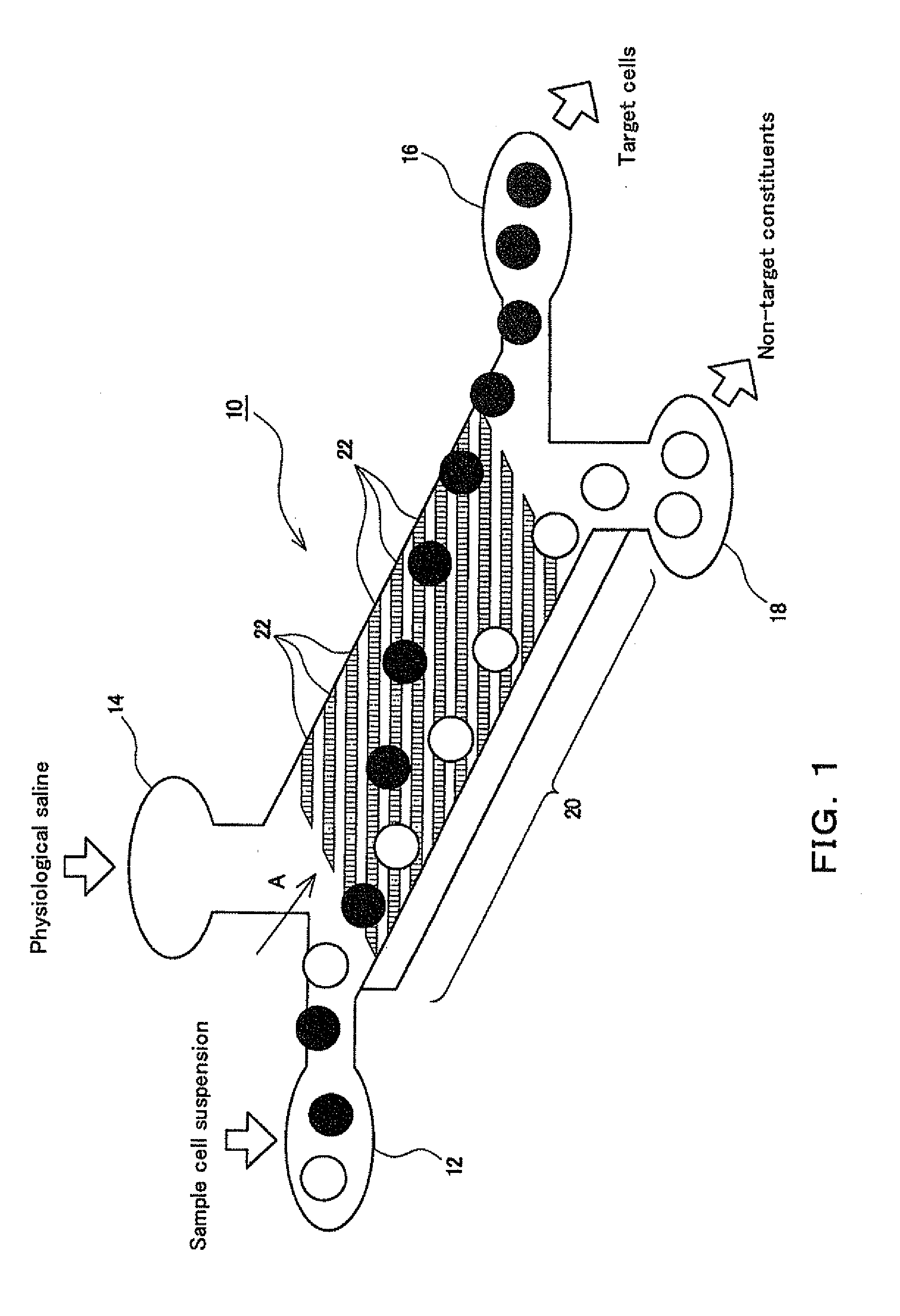
[0059]Fluorescent particles with biotin (excitation: 475 nm) were used as mimic particles of the target cells and fluorescent particles with streptoavidin (excitation: 520 nm) were used as mimic particles of non-target constituents. The sample cell suspension mixed with these mimic particles was supplied from the sample inlet 12 and physiological saline was supplied from the physiological saline inlet 14. When supplying these materials, a syringe pump (CMA400, manufactured by Microdialysis) was used. Each mimic particle (100 particles) passed near the target cell discharging outlet 16 and the non-target constituent outlet 18 was photographed using a monochrome cooled CCD camera (Rolera XR, manufactured by QImaging). The position in the direction perpendicular to the flow path direction on the planar wall portion 20 and the number of each mimic particle were measured.

[0060]In the example, the inclination angle of the adsorbing regions 22 in the form of strips used...

example 3

Cell Separation Test Using Real Cells

[0064]The separation test was performed using human umbilical vein endothelial cells which are real cells as the target cells. The method for producing the cell separation device used in the process is described below.

[0065]First, the liquid flow path 10 having the planar wall portion 20 is formed in the same manner as described in FIG. 8(a) to (e) of Example 1. Next, streptoavidin is fixed to the concavo-convex portion of the planar wall portion 20 via biotin by the same process as Example 1.

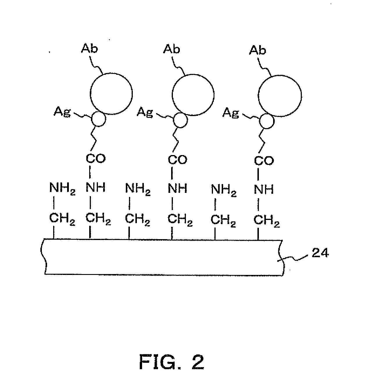
[0066]Then, 1 μg / ml of human CD31 antibodies after biotin labeling is introduced into the liquid flow path 10, which is allowed to stand for 30 minutes, followed by washing with PBS. Thus, the CD31 antibodies can be fixed to streptoavidin fixed to the concavo-convex portion of the planar wall portion 20. As the result, the adsorbing regions 22 in the form of strips in which the adsorbing portions are comprised of the CD31 antibodies are formed.

[0067]Subseque...


PUM


Abstract

A cell separation device which can perform a continuous processing without bonding fluorescent molecules or magnetic particles to the surface of the cell membrane, a cell separation system, and a cell separation method, wherein when a sample cell suspension containing the desired target cells is supplied continuously from a sample inlet and physiological saline is supplied continuously from a physiological saline inlet, the sample cell suspension flows together with the physiological saline in a liquid flow path and an adsorption force acts on the target cells due to affinity bonding from the adsorbing portions of adsorbing regions in the form of strips formed in a planar wall portion. Since the adsorbing regions in the form of strips are disposed in an asymmetric fashion to the flow path direction of the liquid flow path, the adsorption force acting on the target cells has a constituent perpendicular to the flow path direction. As a result, the target cells shown in FIG. 1 collect on one side of the planar wall portion after flowing for a prescribed distance in the liquid flow path and can be separated continuously from the non-target constituents.

Description

BACKGROUND[0001]The present invention relates to a cell separation device, a cell separation system, and a cell separation method to separate desired cells such as stem cells from a sample cell suspension and recover them.[0002]RELATED ART[0003]Conventionally, various techniques for separating and recovering stem cells contained in a sample cell suspension have been proposed. Examples of the technique for separating stem cells include a fluorescence activated-cell separation (FACS) procedure, an immunomagnetic cell separation (IMCS) procedure, and an immunoadsorption procedure. An example of IMCS is disclosed in Japanese Patent Application Laid-Open (JP-A) No. 2006-6166. An example of the immunoadsorption procedure is disclosed in Non-patent document below.[0004][Non-patent document] ADHESION-BASED CELL SORTER WITH ANTIBODY-IMMOBILIZED FUNCTIONALIZED-PARYLENE SURFACE Proc. IEEE Int. Conf. MEMS 2007, Kobe (2007), pp. 27-30 Junichi Miwa, et al.[0005]However, in the case of FACS or IMC...

Claims


Application Information

Patent Timeline
IPC IPC(8): C12N5/02C12M1/00
CPCC12M47/02G01N2015/1006G01N1/405
Inventor SUZUKI, YUJIKASAGI, NOBUHIDENISHIMURA, TAKAHIROMIWA, JUNICHI
Owner THE UNIV OF TOKYO
Learn More