Pulse laser apparatus, terahertz measuring apparatus, and terahertz tomographic apparatus
a laser and terahertz technology, applied in the field of pulse laser apparatus, terahertz measuring apparatus, terahertz tomographic apparatus, can solve the problems of difficult to constitute fiber laser with such a high output, inconvenient operation, and inability to meet the needs of patients,
- Summary
- Abstract
- Description
- Claims
- Application Information
AI Technical Summary
Benefits of technology
Problems solved by technology
Method used
Image
Examples
first exemplary embodiment
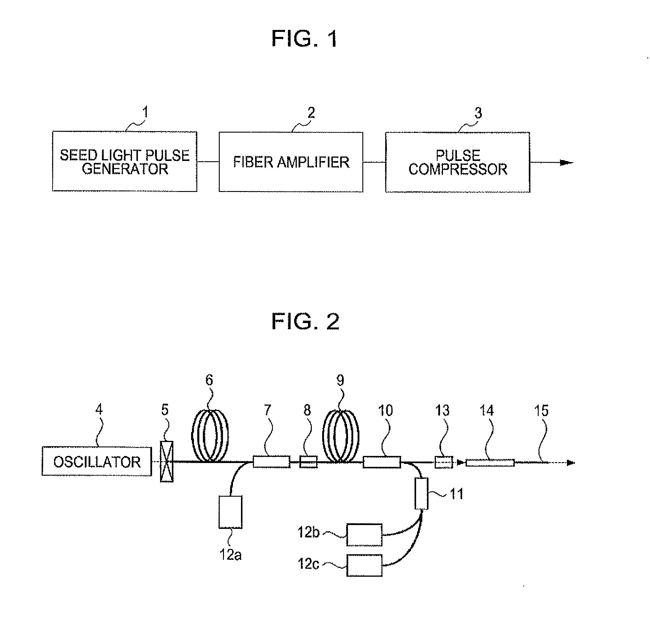
[0075]A THz TDS (Time Domain Spectroscopy) system can be constituted by using the ultrashort pulse laser described above. FIG. 6 is a diagram illustrating a configuration of a terahertz TDS measuring apparatus using the pulse laser apparatus according to a first exemplary embodiment of the present invention. Numeral 60 denotes an output beam of the above-described ultrashort pulse laser including the fiber amplifier, according to the exemplary embodiment of the present invention. The output beam has a wavelength of 1558 nm, an optical output of about 200 mW, and a pulse width of 17 fs. In FIG. 6, dotted lines represent propagation paths of the laser beam, and solid lines represent propagation paths of THz waves. The illustrated apparatus according to the first exemplary embodiment can provide an ultrashort pulse laser of 20 fs or less, having a high output of 100 mW or more and a smaller pedestal in the time domain, which has hitherto been difficult to realize in a femtosecond laser...
second exemplary embodiment
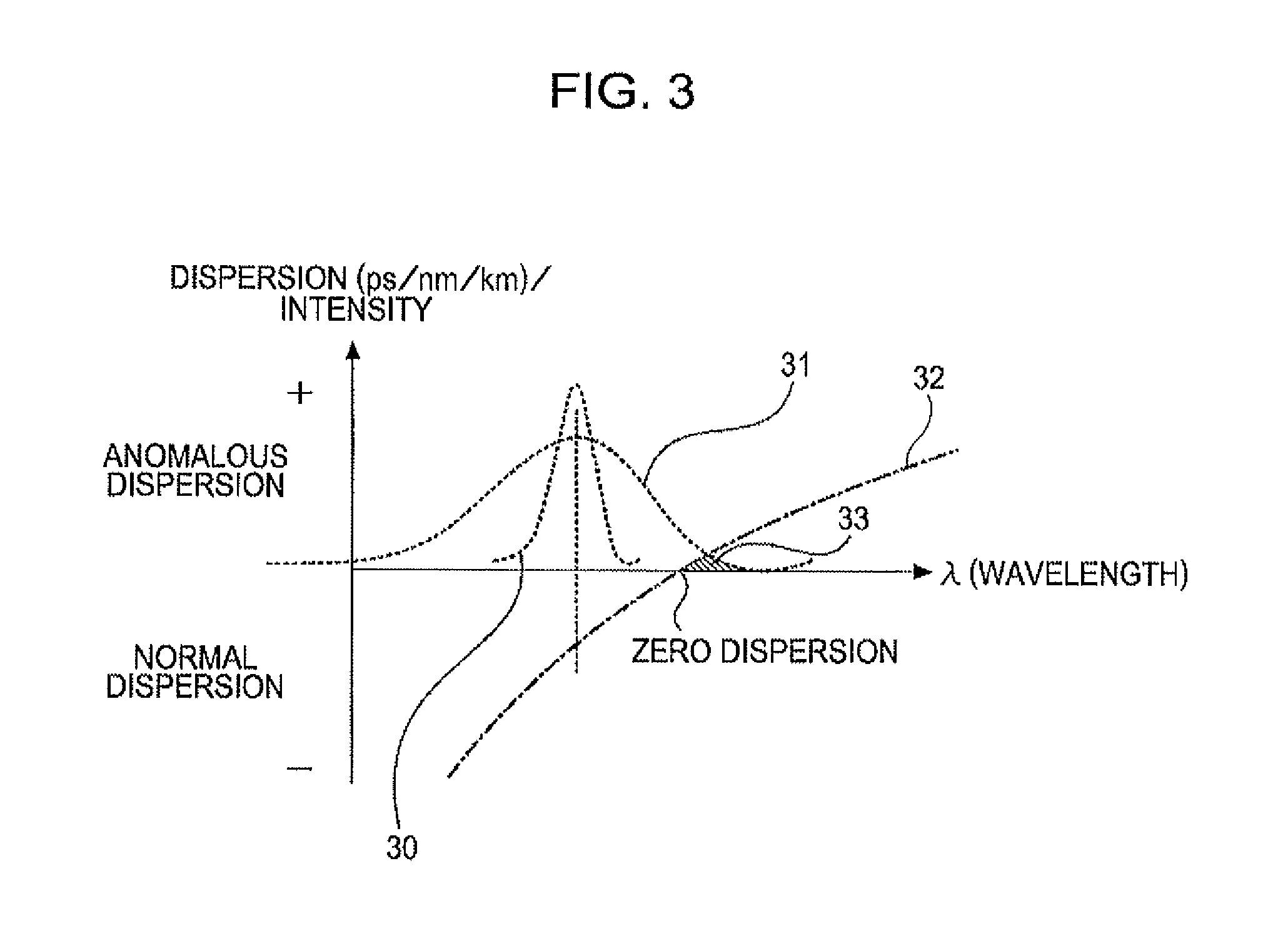
[0082]A second exemplary embodiment of the present invention is constituted such that the bending radius R of the fiber amplifier is adjustable. The wavelength band, the optical power, and the spectrum band required in the THz-TDS system, according to the first exemplary embodiment, differ depending on the specifications of the measuring system. Accordingly, the degree of amplification in the fiber amplifier and the amount of optical energy in the wavelength region longer than the zero-dispersion wavelength also differ depending on the specifications of the measuring system. Further, the degree of amplification and the chirp amount differ due to a variation per lot of the erbium doped fiber.
[0083]In this second exemplary embodiment, the curvature radius R, shown in FIG. 4B, is made variable by an actuator, for example, depending on the required optical power and pulse width. As shown in FIG. 10, a structure for winding a fiber 103 is provided as plural structures 100 to 102 having d...
third exemplary embodiment
[0085]In a third exemplary embodiment of the present invention, a stabilizer based on feedback control is added to the fiber amplifier. In the fiber amplifier, as shown in FIG. 11, a part of the output of the erbium doped fiber is taken out by a branch unit 110. Average power of the taken-out output is monitored by a photodetector 111, and a monitored result is fed back to the polarization controller 8 and a part or all of the excitation lasers 12a to 12c. On that occasion, an output variation of the erbium doped fiber attributable to the excitation laser has a relatively quick time component (on the order of several tens minutes or shorter) in its large part, while an output variation thereof attributable to the polarization has a relatively slow time component (on the order of hour or longer) in its large part. Therefore, a low-pass filter (or an integrator) 112 is inserted into a path for a feedback signal introduced to the polarization controller 8, and a high-pass filter 113 is...
PUM
 Abstract
Description
Claims
Application Information
 - R&D
- Intellectual Property
- Life Sciences
- Materials
- Tech Scout
- Unparalleled Data Quality
- Higher Quality Content
- 60% Fewer Hallucinations
Browse by: Latest US Patents, China's latest patents, Technical Efficacy Thesaurus, Application Domain, Technology Topic, Popular Technical Reports.
© 2025 PatSnap. All rights reserved.Legal|Privacy policy|Modern Slavery Act Transparency Statement|Sitemap|About US| Contact US: help@patsnap.com


