[0003]In a conductive network, the conductivity can be guided by percolation theory. Mathematically, percolation can be described as the following: in an infinite network, there is a path of connected points of infinite length “through” the network. With increasing
population of the conducting points, there exists a critical number above which at least one conducting pathway forms within the network. The critical point is called
percolation threshold which is a particle-size and geometry-
dependent parameter for composites. Generally, smaller particles allow for a lower
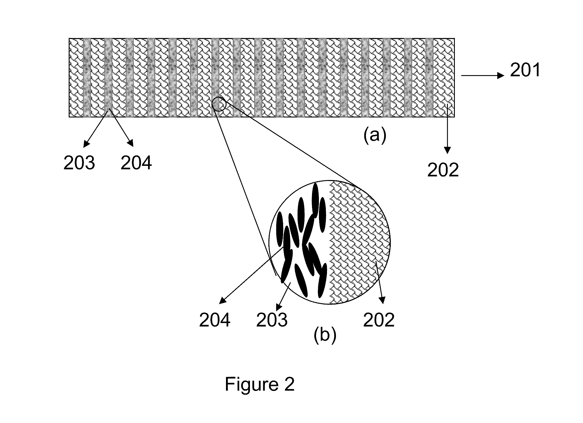
percolation threshold, due to the fact that average particle distance decreases with particle size, given the same volume ratio, which helps to build the connection pathway of particles through the whole composite. Particle shape is another important factor. It has been shown, both theoretically and experimentally, that percolation threshold can be significantly decreased by using high
aspect ratio particles.
[0007]Another area where composites could be applied is for use as temporary bonding materials for
wafer processing. To accommodate the ever increasing demand for smaller
IC devices in
cell phones, music players, cameras etc, it has become common to
grind the fully processed device wafers to be thinner. After the device
wafer is processed on the front side, it is coated with a temporary bonding
adhesive on the front and further processed on the back (
thinning,
etching, metallization, etc.). The device
wafer is then detached from the temporary bonding materials. The
wafer thinning is often done using aggressive methods that generate a substantial amount of heat, which inevitably raises the wafer temperature, sometimes to as high as 300° C. Better heat dissipation may reduce the device temperature and / or allow for more aggressive
thinning methods to reduce
processing times. Incorporation of thermal conductive fillers could help to increase the
thermal conductivity of the temporary bonding materials. Using traditional conductive fillers to effectively increase the thermal conductivity of the composite typically requires high levels of loading, which significantly decrease the
bonding strength of the composites. Therefore, it would be useful to develop a composite with low filler loading and high thermal conductivity for better temporary bonding materials.
[0011]Electric charges, induced by contact, pressure, or heat, build up on an object with low electrical conductivity. Rapid
discharge of the static charge build up can generate a large
electric current or an electrical spark, which may be extremely harmful to electronic devices, around flammable and ignitable materials, and in
space exploration. Increasing the
surface conductivity of the materials helps to reduce the charge build up and dissipates static charge to the ground constantly.
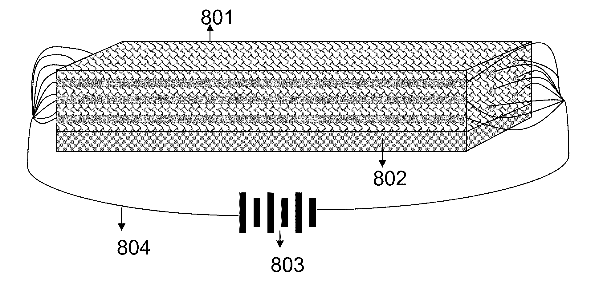
[0020]An example non limiting implementation provides a multi-component
electrical conductor with a first component that is a matrix
polymer, a second component that is a
low melting point material immiscible with the first component; and a third component that is a filler material with higher electrical conductivity than the first and second components. The third component is dispersed into the second component and the second component is dispersed within the
polymer matrix. The third component provides enhanced electrical conductivity to the multi-component
electrical conductor. In addition an example multi-component
electrical conductor may comprise an optically transparent first component and an optically transparent second phase material and a third component that is a filler material with higher electrical conductivity than the first and second components. The refractive indices of the polymer matrix and the second phase material may be similar to each other to minimize internal reflection and maximize transparency.
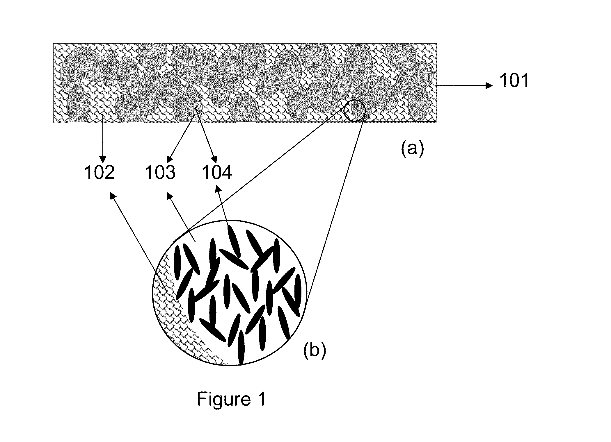
[0021]One exemplary non-limiting illustrative embodiment provides a composite composition made up of multiple components. The
multiple component system include, at least two components, preferably three components, and more components in certain applications. This
multiple component system includes polymers and fillers to improve the thermal and / or electrical conductivity of the matrix material in at least one dimension.
[0032]One exemplary non-limiting illustrative embodiment provides having a high aspect ratio filler chemically bonded with the
low melting point polymer that is in-situ polymerized. The chemical bonds promote the alignment of the high aspect ratio fillers as the
low melting point polymer melt and flow at the
working temperature.

