Proton conducting electrolyte membranes having nano-grain YSZ as protective layers, and membrane electrode assemblies and ceramic fuel cells comprising same

a technology of proton conducting electrolyte and protective layer, which is applied in the direction of cell components, final product manufacturing, sustainable manufacturing/processing, etc., can solve the problems of low compatibility, slow initialization of high-temperature fuel cells, and high difference between operating temperature and starting temperature, so as to achieve high compatibility

Inactive Publication Date: 2011-10-27
SAMSUNG ELECTRONICS CO LTD +1
View PDF1 Cites 26 Cited by
  • Summary
  • Abstract
  • Description
  • Claims
  • Application Information

AI Technical Summary

Benefits of technology

[0019]The ceramic protective layer may prevent penetration of carbon dioxide.

Problems solved by technology

However, in such high temperature fuel cells, the difference between operating temperature and starting temperature is very high and thus the initialization of high temperature fuel cells is slow.
Also, stress due to the difference in thermal deformation of each material is accumulated while turning on and off a high temperature fuel cell so that durability of the fuel cell decreases.
In addition, high-cost conductive materials (for example, an INCONEL® alloy, Special Metals Corp.
In addition, since a glass-based material should be used as a sealing material, it is difficult to manufacture a high temperature fuel cell and the high temperature fuel cell has weak resistance to shocks.
In addition, sealing may be more easily performed at a temperature of around 200° C. However, even if the thickness of an oxygen ion conductor used in a high temperature fuel cell is reduced, resistance to ionic conduction is very high at a temperature of 300° C. or less and, thus, it is difficult to use the oxygen ion conductor.
However, since carbonation may occur after barium zirconate or barium cerate reacts with CO2 (BaZrO3+CO2→BaCO3+ZrO2; BaCeO3+CO2→BaCO3+CeO2) and sintering of BYZ or BYC is difficult, forming a fuel cell using such a ceramic proton conductor is unsatisfactory.

Method used


Image

  • Proton conducting electrolyte membranes having nano-grain YSZ as protective layers, and membrane electrode assemblies and ceramic fuel cells comprising same
  • Proton conducting electrolyte membranes having nano-grain YSZ as protective layers, and membrane electrode assemblies and ceramic fuel cells comprising same
  • Proton conducting electrolyte membranes having nano-grain YSZ as protective layers, and membrane electrode assemblies and ceramic fuel cells comprising same

Examples


preparation examples 1 through 3

[0079]In order to verify proton conductivity of nano-grain YSZ (8 mol % Y2O3-stabilized ZrO2), the change in deuterium concentration according to thicknesses of YSZ layers was analyzed, wherein the YSZ layers include nano-grain YSZ thin layers (thickness: about 100 nm) each having an average crystal grain size of about 25 nm that are deposited by using ALD (Preparation Example 1) and PLD (Preparation Example 2), and a micro-grain YSZ thin layer (thickness: about 500 μm) having an average crystal grain size of about 10 μm formed by using sintering (Preparation Example 3) on a Si3N4 layer having a thickness of about 100 nm formed on a Si wafer having a thickness of about 350 μm.

[0080]The nano-grain YSZ thin layer according to Preparation Example 1 was deposited by carrying out the following processes in a reaction chamber:

[0081](1) A Si3N4 substrate maintained at 250° C. was exposed to tetrakis(dimethylamido)zirconium (heating temperature of 75° C.) gas in a reaction chamber,

[0082](2)...

example 1

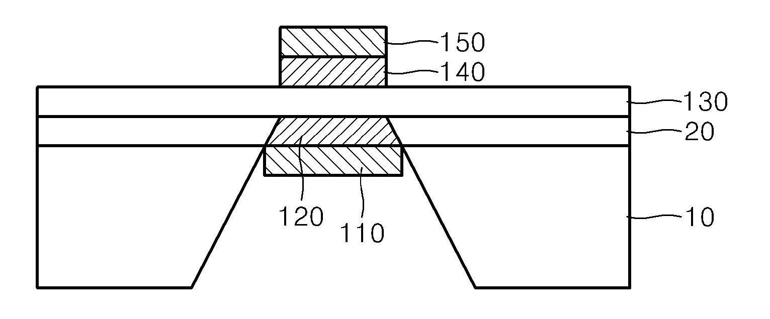
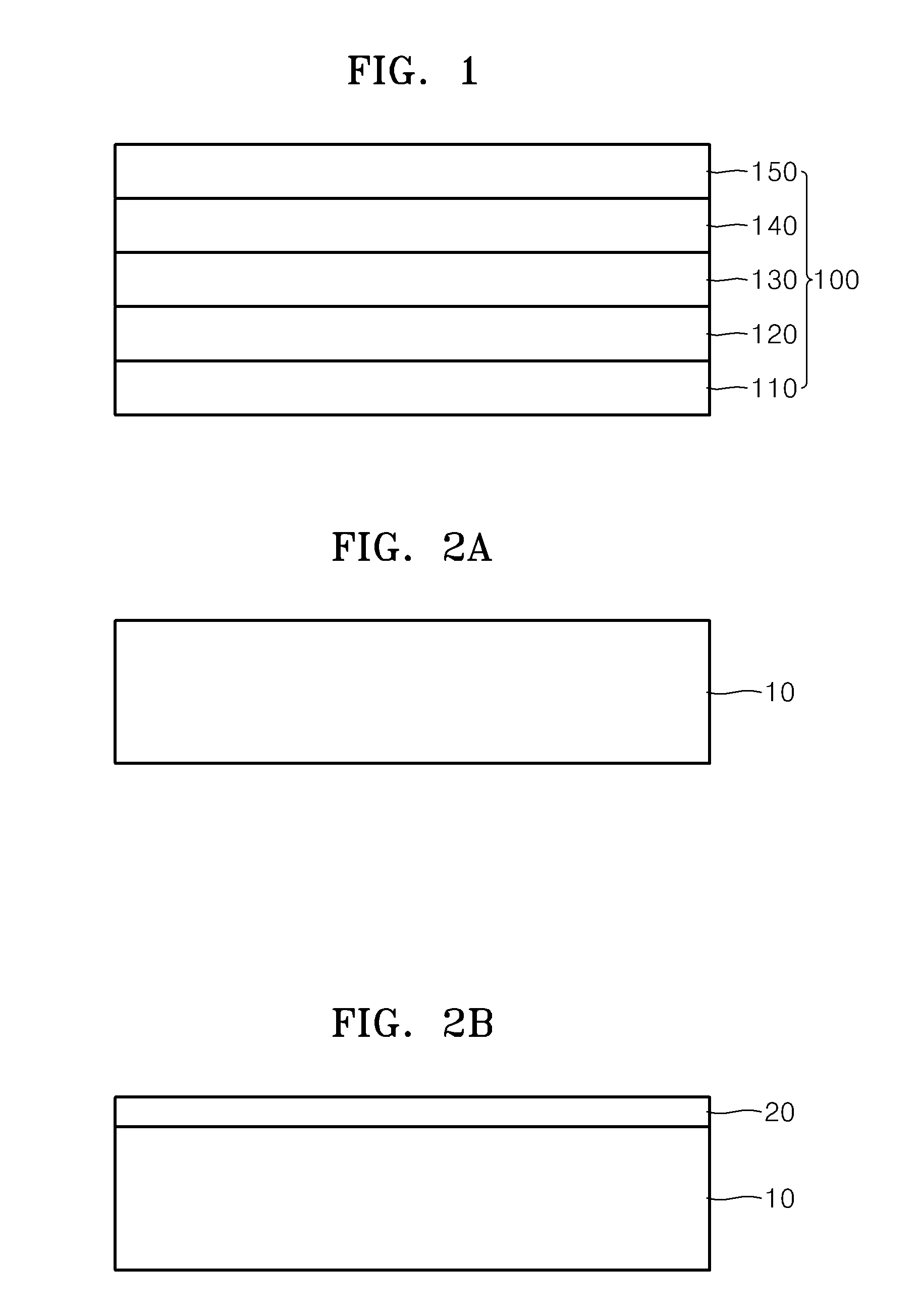
[0095]A silicon nitride layer having a thickness of about 100 nm, as an etch-stop layer, was deposited on a silicon substrate heated to about 800° C. by using low pressure chemical vapor deposition (LPCVD) (FIGS. 2A and 2B).

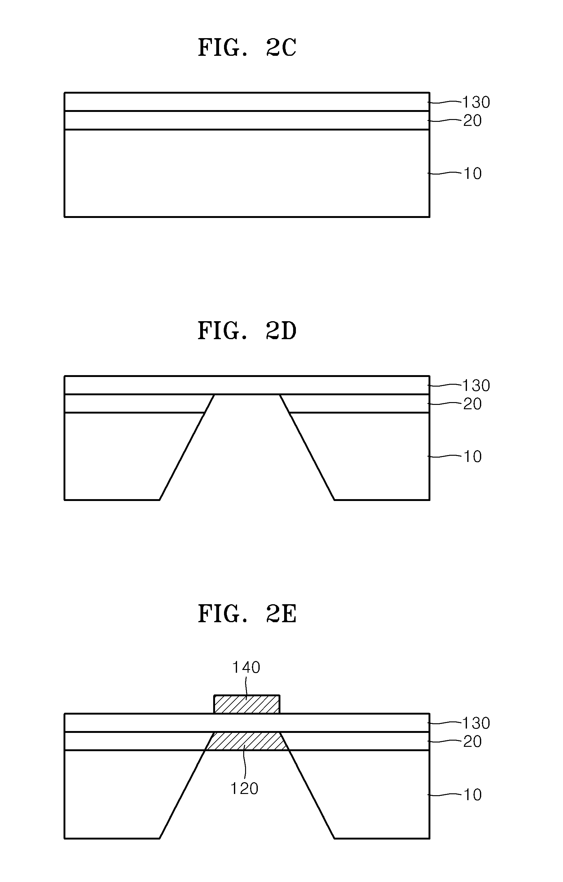
[0096]A proton conducting solid oxide electrolyte thin layer (BYZ; Y:BaZrO3) was deposited to a thickness of about 100 nm on the silicon nitride layer (FIG. 2C).

[0097]A predetermined area of the back side of the silicon substrate was exposed by using photolithography and then the silicon substrate was impregnated with 30 weight % of a KOH solution for about 4 hours, thereby first removing the silicon substrate. Then, the exposed silicon nitride layer was removed by using drying etching, in which SF6 and O2 were used, in a reaction chamber, thereby exposing the back side of the BYZ ceramic electrolyte layer (FIG. 2D).

[0098]ALD, in which the following processes were repeated, was performed on the obtained silicon substrate in a reaction chamber and thus the nano-gr...

example 2

[0101]A MEA was manufactured as in Example 1, except that the anode side ceramic protective layer 120 and the cathode side ceramic protective layer 140 each including a nano-grain YSZ having an average crystal grain size of about 25 nm and a thickness of about 5 nm were formed by using PLD, instead of using ALD:

[0102]In a reaction chamber, in which the inside of the chamber was evacuated and then the oxygen partial pressure was adjusted to about 100 mTorr, KrF laser having pulse energy of 3.0 J / cm2 was beamed toward a YSZ target so as to form a YSZ plasma. Then, the nano-grain YSZ thin layer was deposited on a silicon substrate that was spaced apart from the target by 6.5 cm and was maintained at 400° C.


PUM

PropertyMeasurementUnit
crystal grain sizeaaaaaaaaaa
temperatureaaaaaaaaaa

Abstract

A proton conducting electrolyte membrane comprising a ceramic electrolyte layer including an inorganic proton conductor and a ceramic protective layer formed on at least one surface of the ceramic electrolyte layer and having proton conductivity; a membrane electrode assembly including the proton conducting electrolyte membrane; and a proton conducting ceramic fuel cell including the membrane electrode assembly. In the proton conducting electrolyte membrane, the ceramic protective layer may have an improved chemical bond with the ceramic electrolyte layer compared with a Pd metal protective layer, such that interlayer delamination may be lessened. Also, compared with a Pd metal protective layer, the ceramic protective layer is more appropriate for ceramic electrolytes such as BYZ and BYC that transmit protons or simultaneously transmit protons and oxygen ions used in a fuel cell operating at a temperature range of about 200 to about 500° C., for example, about 250 to about 500° C.

Description

CROSS-REFERENCE TO RELATED APPLICATIONS[0001]This application claims the benefit of Korean Patent Application Nos. 10-2010-0038181, filed on Apr. 23, 2010, 10-2010-0080000, filed on Aug. 18, 2010, and 10-2011-0013682, filed on Feb. 16, 2011, all in the Korean Intellectual Property Office, the disclosures of which are incorporated herein in their entireties by reference.BACKGROUND[0002]1. Field[0003]Aspects of the present disclosure relate to proton conducting electrolyte membranes, and membrane electrode assemblies and fuel cells including the same, and more particularly, to proton conducting electrolyte membranes having nano-grain yttrium-stabilized zirconia (YSZ) as ceramic protective layers thereof, as well as membrane electrode assemblies and ceramic fuel cells including the same.[0004]2. Description of the Related Art[0005]In a fuel cell, an electrolyte is interposed between two electrodes, each formed of an electrochemical catalyst including a porous metal or carbon. It is cal...

Claims


Application Information

Patent Timeline
Patent Type & Authority Applications(United States)
IPC IPC(8): H01M8/12H01M8/10B82Y99/00
CPCB82Y30/00B82Y40/00H01M4/8871H01M4/9033H01M4/905H01M8/1213Y02E60/525H01M8/126H01M8/1286H01M2300/0071H01M2300/0094Y02E60/521H01M8/1253Y02P70/56
Inventor KANG, SANG-KYUNPARK, JOONG-SUNGUR, TURGUT M.KIM, YOUNG-BEOMPRINZ, FRIEDRICH B.SHIM, JOON-HYUNG
Owner SAMSUNG ELECTRONICS CO LTD
Why Eureka
Try Eureka