

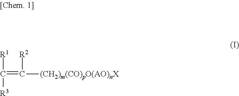
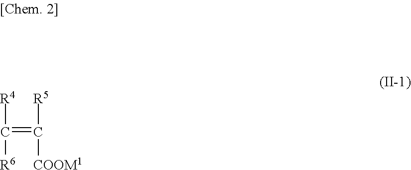
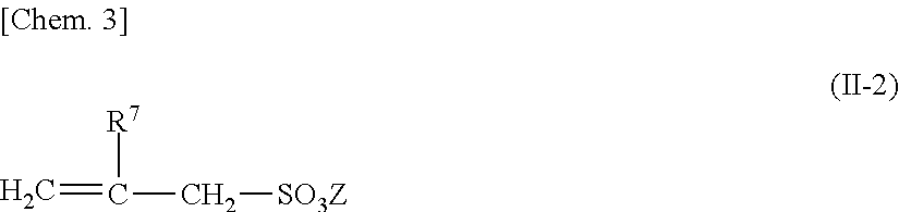
Shrinkage-reducing agent for hydraulic material and shrinkage-reducing agent composition for hydraulic material
a technology of shrinkage reducing agent and hydraulic material, which is applied in the preparation of organic compounds, coatings, other chemical processes, etc., can solve the problems of reducing safety, reducing strength or durability, and dissolving moisture remaining in materials, so as to suppress the generation of cracks, suppress the strength reduction of cured articles, and excellent shrinkage-reducing function
- Summary
- Abstract
- Description
- Claims
- Application Information
AI Technical Summary
Benefits of technology
Problems solved by technology
Method used
Image

Examples
production example 1
Production of Copolymer (1)
[0184]First, 200.2 g of water were charged into a reactor made of glass provided with a temperature gauge, a stirring machine, a dropping apparatus, a nitrogen-introducing pipe, and a reflux condenser. Next, the air in the reactor was replaced with nitrogen under stirring, and then the inside of the reactor was heated to 80° C. under a nitrogen atmosphere. A monomer aqueous solution prepared by mixing 225.2 g of a methoxy polyethylene glycol monoacrylate (having an average added mole number of ethylene oxide of 25), 44.8 g of methacrylic acid, 450 g of water, and 2.2 g of 3-mercaptopropionic acid as a chain transfer agent was dropped to the reaction vessel over 4 hours, and 60 g of a 5.2% aqueous solution of ammonium persulfate were dropped to the reaction vessel over 5 hours. After the termination of the dropping of the 5.2% aqueous solution of ammonium persulfate, the temperature was continuously maintained at 80° C. for an additional 1 hour so that a po...
production example 2
Production of Copolymer (2)
[0185]First, 200.2 g of water were charged into a reactor made of glass provided with a temperature gauge, a stirring machine, a dropping apparatus, a nitrogen-introducing pipe, and a reflux condenser. Next, the air in the reactor was replaced with nitrogen under stirring, and then the inside of the reactor was heated to 80° C. under a nitrogen atmosphere. A monomer aqueous solution prepared by mixing 239.9 g of a methoxy polyethylene glycol monoacrylate (having an average added mole number of ethylene oxide of 25), 20.1 g of methacrylic acid, 450 g of water, and 2.2 g of 3-mercaptopropionic acid as a chain transfer agent was dropped to the reaction vessel over 4 hours, and 60 g of a 5.2% aqueous solution of ammonium persulfate were dropped to the reaction vessel over 5 hours. After the termination of the dropping of the 5.2% aqueous solution of ammonium persulfate, the temperature was continuously maintained at 80° C. for an additional 1 hour so that a po...
production example 3
Synthesis of Copolymer Aqueous Solution PC-1 Corresponding to Polymer as Component B
[0186]The copolymer (1) obtained in Production Example 1 and the copolymer (2) obtained in Production Example 2 were mixed at a weight ratio “copolymer (1) / copolymer (2)” in terms of a solid content of 30 / 70. Thus, a copolymer aqueous solution PC-1 corresponding to a polymer as the component B was obtained.
PUM
| Property | Measurement | Unit |
|---|---|---|
| mol % | aaaaa | aaaaa |
| mol % | aaaaa | aaaaa |
| flow rate | aaaaa | aaaaa |
Abstract
Description
Claims
Application Information