Pressure sensing or force generating device

a technology of pressure sensing and force generating device, which is applied in the direction of generator/motor, force measurement using piezo-resistive materials, instruments, etc., can solve problems such as drawbacks and limitations, and achieve the effects of less likely to cause trauma upon contact, reduced device count, and dense device packing

Active Publication Date: 2012-03-08
MICROPEN TECH CORP
View PDF3 Cites 188 Cited by
  • Summary
  • Abstract
  • Description
  • Claims
  • Application Information

AI Technical Summary

Benefits of technology

[0015]Piezoelectric or capacitive materials have been used as pressure sensors/force generating devices. Piezoelectric materials have been incorporated in catheters for some time. However, these have drawbacks and limitations as discussed supra. The present invention provides multiple benefits over the state of the art. The present invention produces pressure sensitive and force generating devices that are compact, streamlined,

Problems solved by technology

However, these have drawbacks an

Method used


Image

  • Pressure sensing or force generating device
  • Pressure sensing or force generating device
  • Pressure sensing or force generating device

Examples


example 1

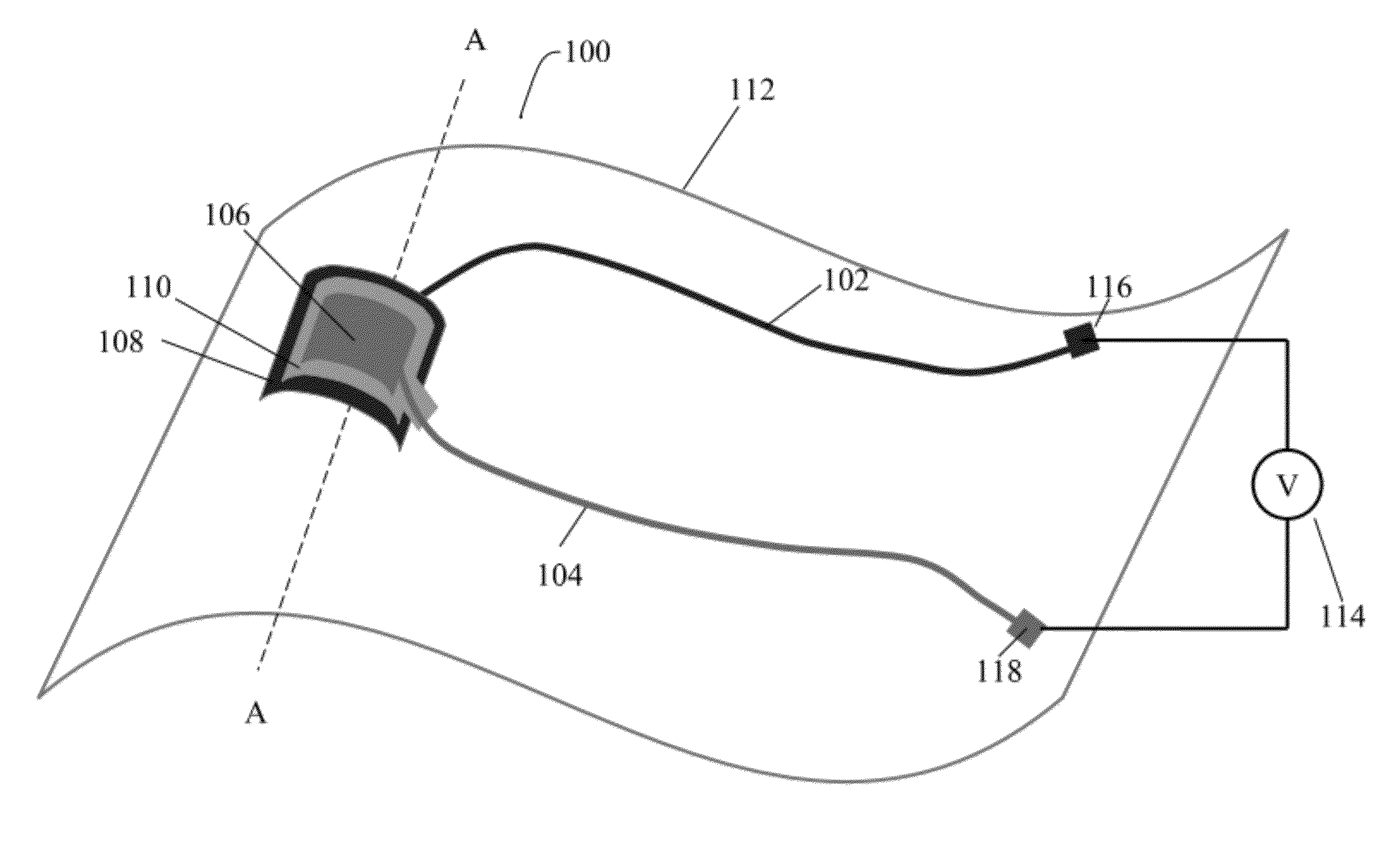
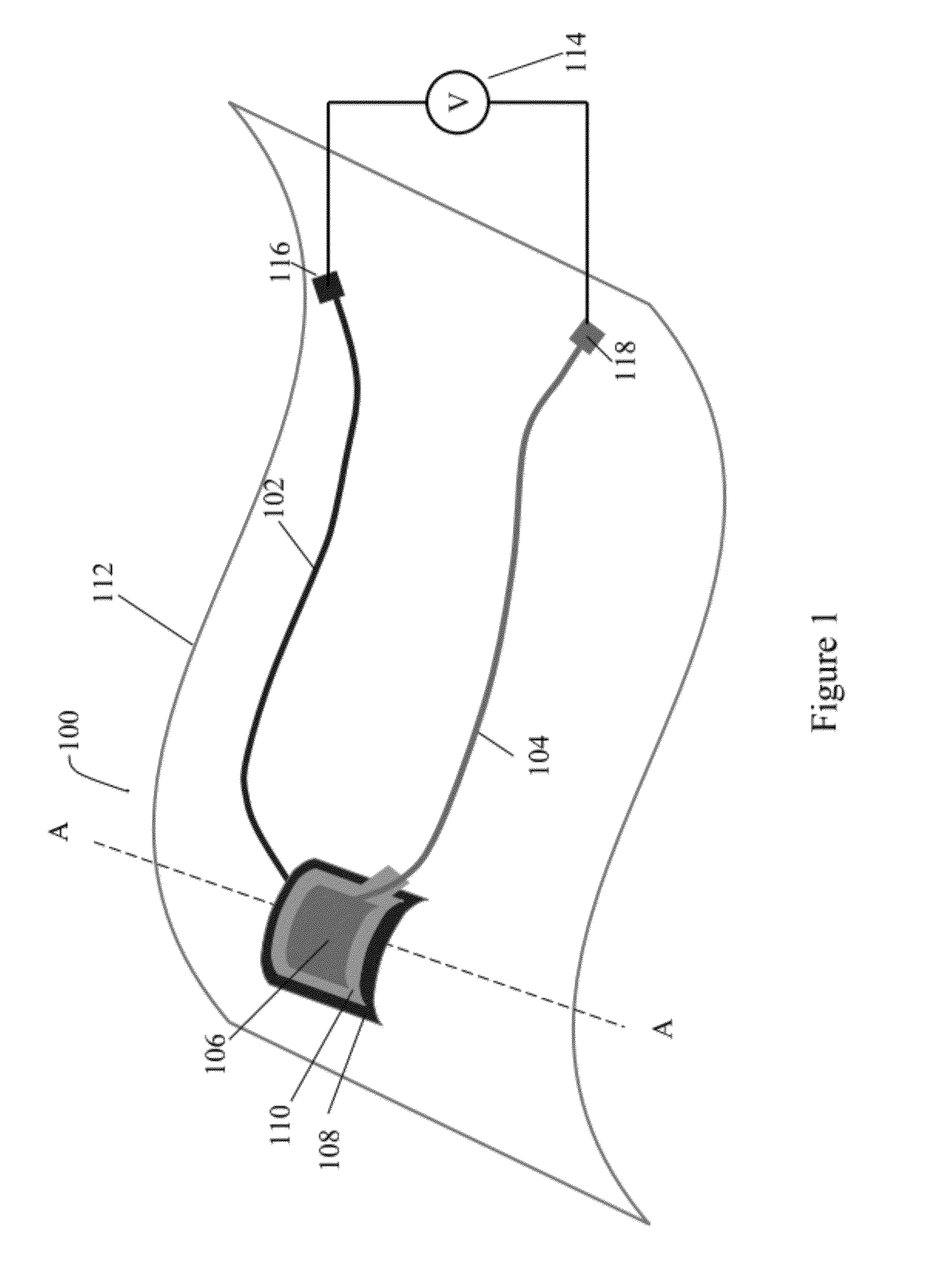
Piezoelectric Polymer Pressure Sensor on an Endotracheal Tube

[0082]Silver ink was prepared by dissolving poly(vinyl chloride) (Colorite® Flexchem 5051-02) at a level of 16.7% by weight in cyclohexanone. Silver flake (10 μm, >99.9%, Sigma-Aldrich) was added to yield a ratio of silver:poly(vinyl chloride) of 90:10. The total solids were 68% by weight. In order to enable thorough mixing, the materials were combined using a planetary high shear mixer (Kurabo Mazerustar KK-50S).

[0083]Piezoelectric polymeric ink was prepared by dissolving a polyvinylidene fluoride-trifuoroethylene (PVDF-TrFE) copolymer (75:25 mole ratio; Kynar copolymer, Measurement Specialties Inc) in n-methyl pyrrolidone to make a 30% solution.

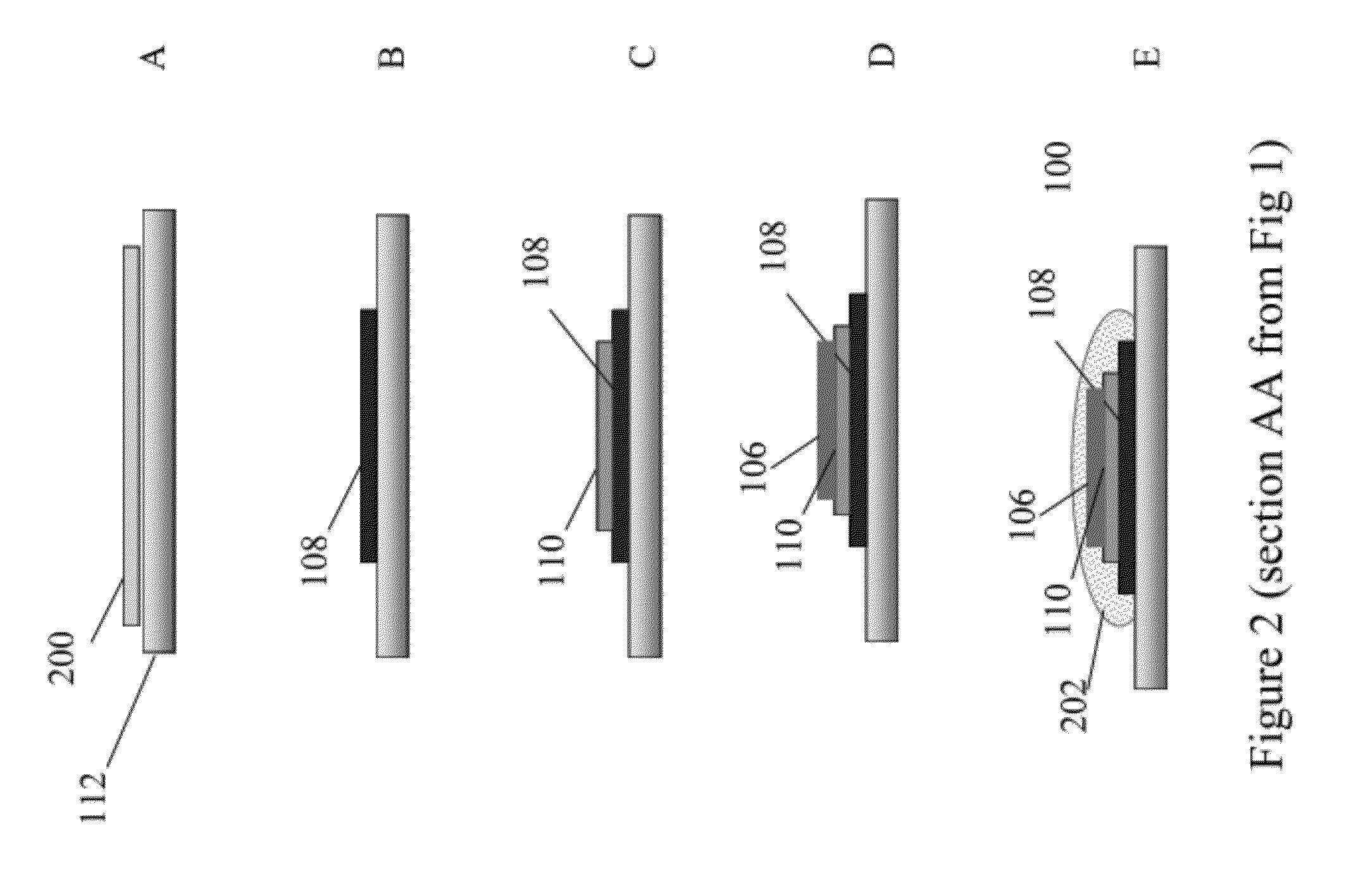
[0084]Using the silver ink, a bottom electrode and lead were written on a commercially available standard endotracheal tube (Unomedical Air Management, Magill, HVLP cuff) and cured at 100° C. for 30 minutes. Then, three layers of the piezoelectric polymer were written onto the sur...

example 2

Piezoelectric Polymer Pressure Sensor on Cuff with Overcoat

[0086]A PVDF-TrFE piezoactive layer with top and bottom electrodes was prepared in a manner identical to Example 1, except that it was positioned on the cuff of the endotracheal tube and was covered with a UV-curable medical polymeric encapsulant (Dymax 1-20323; Dymax Corporation) which was subsequently cured via ultraviolet irradiation.

example 3

Piezoelectric Ceramic Pressure Sensor on Tube

[0087]A piezoelectric sensor with electrodes was prepared identically to Example 1, except that the piezoelectric material was BaTiO3. The BaTiO3 ink was prepared by dissolving poly(vinyl chloride) (high molecular weight, Aldrich) at a level of 13% by weight in dimethylacetamide, and adding BaTiO3 particulate (Barium titanate (IV), 3 was 31.25:68.75 and the total solids were 30.1% by weight. The ink was deposited in two layers and each layer was cured at 80° C. for 30 minutes to yield a total thickness of approximately 12 μm.

[0088]The sample was connected and poled identically to Example 1, and exhibited a piezoelectric response of about 20 mV when flexed.


PUM

PropertyMeasurementUnit
Thicknessaaaaaaaaaa
Thicknessaaaaaaaaaa
Pressureaaaaaaaaaa

Abstract

In one aspect, the present invention relates to a pressure sensing/force generating device comprising a non-planar substrate, a printed pressure sensitive element comprising (a) a piezoelectric material containing ink composition capable of producing a piezoelectric effect/piezoresistive effect and/or (b) a dielectric material containing ink composition capable of producing a capacitive effect. It also includes a first printed electrode comprising a conductive ink composition, and a second printed electrode comprising a conductive ink composition. The first and second electrodes are in electrical contact with the printed pressure sensitive element. The first and second printed electrodes and the printed pressure sensitive element collectively form a pressure sensitive junction, which is coupled to the non-planar substrate. The present invention further relates to medical devices comprising the pressure sensing/force generating device and methods of making such devices.

Description

[0001]This application claims the benefit of U.S. Provisional Patent Application Ser. No. 61 / 380,965, filed Sep. 8, 2010, which is hereby incorporated by reference in its entirety.FIELD OF THE INVENTION[0002]The present invention is related to a pressure sensing or force generating device.BACKGROUND OF THE INVENTION[0003]Accurate measurements of pressure, stress, force, or deflection are required in many technical applications. Piezoactive materials generate a change in resistance or produce a voltage upon application of pressure or deformation and are a convenient choice to enable such measurements. These materials may also be used as actuators or force generators which exhibit deflection or vibration as a voltage is applied. Similarly, changes in capacitance can also be used to measure pressure, stress, force or deflection. Most capacitors are designed to maintain a fixed physical structure. However, various factors, such as pressure, can change the structure of the capacitor, and...

Claims


Application Information

Patent Timeline
IPC IPC(8): G01L1/18G01L1/14H01L41/22H02N2/00
CPCH01L41/081H01L41/094H01L41/1132H01L41/1136Y10T29/42H01L41/317G01L1/142G01L1/16G01L1/18H01L41/314H10N30/10513H10N30/2042H10N30/302H10N30/306H10N30/074H10N30/077
Inventor SHAW-KLEIN, LORI J.
Owner MICROPEN TECH CORP
Why Eureka
Try Eureka