Light energy conversion material

a technology of light energy and conversion materials, which is applied in the field of light energy conversion materials, can solve the problems of insufficient amount of electron donor introduced in the pore, insufficient chemical energy conversion reaction, and inability to achieve the effect of increasing and improving the efficiency of light energy conversion

Inactive Publication Date: 2012-07-19
TOYOTA CENT RES & DEV LAB INC
View PDF0 Cites 6 Cited by
  • Summary
  • Abstract
  • Description
  • Claims
  • Application Information

AI Technical Summary

Benefits of technology

[0009]The present invention is made in consideration of the problems of the prior art. An object of the present invention is to provide a light energy conversion material which can advance a light energy conversion reaction with a high efficiency, resulting in the significant improvement in the light energy conversion efficiency, and, further, which can improve the physical stabilities of an electron donor and an electron acceptor to give the light conversion material a sufficient durability.
[0010]The present inventors have devoted themselves to keen studies so as to achieve the above object. As a result, the present inventors have discovered the following facts, and then completed the present invention. The light energy conversion material is obtained by using a porous material including an electron donor in a skeleton thereof, and an electron acceptor is disposed in at least one portion among a pore, the skeleton and the outer circumference of the porous material. The light energy conversion material can surprisingly advance a light energy conversion reaction with a high efficiency, resulting in the significant improvement in the light energy conversion efficiency, and further can improve the physical stabilities of the electron donor and the electron acceptor to give the light conversion material a sufficient durability.
[0018]For these reasons, the porous material including the electron donor in the skeleton is used in the present invention. Accordingly, many of the electron donors are exposed to the surface of the pore of the porous material. When the electron acceptors are disposed on the surface of the porous material, the state where the pair of the electron donor and the electron acceptor is disposed in a high density is formed. Therefore, when the light energy is absorbed, the occurrence of electrons and holes by the charge separation is accelerated. As a result, the electron transfer efficiency is improved, and thereby the light energy conversion efficiency is significantly improved. The porous material including the electron donor in the skeleton has a high light-energy-absorption efficiency because the electron donors are present in the skeleton in a high density. Moreover, the energy excited by the absorption of the light energy can be transferred in the skeleton of the porous material, and thereby the electron transfer efficiency to the electron acceptor is improved. Furthermore, such a transfer efficiency of the excited energy in the skeleton depends on the structure of the porous material. Therefore, the use of the porous material having a more regularly arranged structure allows the light energy conversion efficiency to be improved. Still furthermore, the physical stabilities of the electron donor and the electron acceptor are improved by fixing the electron acceptor in the narrow space such as the pore and the skeleton of the porous material including the electron donor in the skeleton. As a result, the durability of the light conversion material is improved.
[0019]The present invention makes it possible to provide a light energy conversion material which can advance a light energy conversion reaction with a high efficiency, resulting in the significant improvement in the light energy conversion efficiency, and, further, which can improve the physical stabilities of an electron donor and an electron acceptor to give the light conversion material a sufficient durability.

Problems solved by technology

On the other hand, since the photoactive pigment and the electron acceptor were also disposed in the pore space, it is spatially difficult to introduce a sufficiently large amount of the electron donor in the pore.
Consequently, the introduced amount of the electron donor is not always sufficient.
Even if the pore space is filled with the sufficient amount of the photoactive substance and the electronic substance in the light energy conversion material, a chemical energy conversion reaction is not always sufficiently advanced using the pore space as a reaction field.
Thus the energy conversion efficiency is not always sufficient.

Method used


Image

  • Light energy conversion material
  • Light energy conversion material
  • Light energy conversion material

Examples


examples

[0109]The present invention will more specifically be described below based on examples and comparative example. However, the present invention is not limited to the following examples. (Synthesis Example 1: Synthesis of Crystalline Powders of Silica Porous Material Modified by Biphenyl Group (BiPh-HMM))

[0110]First, trimethyloctadecylammonium chloride (surfactant: 1.83 g, 5.26 mol) was dissolved in a mixed liquid of water (100 ml) and a 6M aqueous solution of sodium hydroxide (10 g) to obtain a mixed solution. Then, 4,4′-bis(triethoxysilyl)biphenyl (2.00 g, 4.18 mol) was added dropwise into the obtained mixed solution while stirring at room temperature. Thereafter, the irradiation with ultrasonic waves for 20 minutes and the stirring were repeated to the mixed solution. Subsequently, the solution was stirred for 24 hours at room temperature to obtain a reaction solution. After that, the reaction solution was left at rest at a temperature condition of 98° C. for 48 hours. Then, the r...

example 1

[0119]First, the BiPh-HMM crystalline powders (0.4 g, 1.56 mmol) obtained in Synthesis example 1 was added to a solution prepared by dissolving the 4,4′-bipyridine derivative (100 mg, 0.136 mmol) obtained in Synthesis example 3 in water-containing acetonitrile (8 ml) . Then, the mixture was treated with ultrasonic waves at room temperature for 1 minute. Thereafter, the mixture was stirred while heating at a temperature condition of 70° C. for 2 hours to form a precipitate. Subsequently, the precipitate obtained in the above manner was filtered, washed with water, and further washed with ethanol. Thereafter, the precipitate was dried in vacuum to obtain 0.462 g of crystalline powders of BiPh-HMM modified by viologen (SiVSi(I)-BiPh-HMM).

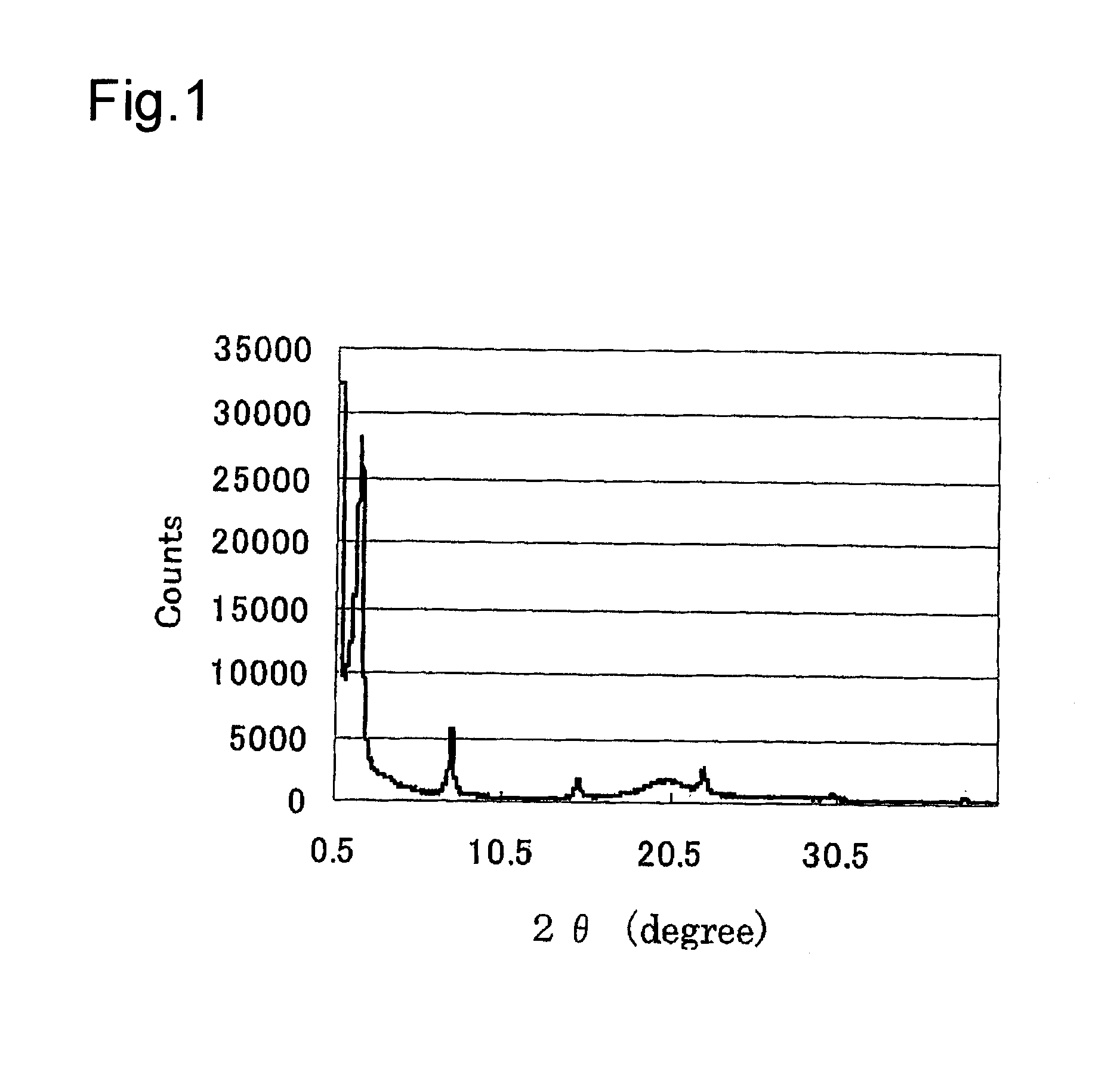
[0120]The SiVSi(I)-BiPh-HMM obtained in the above manner was measured by the X-ray diffraction. FIG. 4 shows the XRD pattern of the SiVSi(I)-BiPh-HMM. From the result shown in FIG. 4, a regularly arranged mesoporous structure (d=45.04 Å) was recognized...

example 2

[0123]The SiVSi(I)-BiPh-HMM obtained in Example 1 (50 mg) was suspended in a saturated NH4PF6 aqueous solution (1 ml) to produce a suspended liquid. The produced suspended liquid was stirred at room temperature for one day. Thereafter, the suspended solid in the suspended liquid was filtered, washed with water, further washed with ethanol, and dried in vacuum to ion-exchange the counter anion of the viologen from iodine ions (I−) to hexafluorophosphate ion (PF6−). Then, to completely carry out such an ion-exchange, the same operation was repeated twice to obtain 32.6 mg of crystalline powders of BiPh-HMM modified by viologen (SiVSi(PF6)-BiPh-HMM).


PUM

PropertyMeasurementUnit
pore diameteraaaaaaaaaa
thicknessaaaaaaaaaa
pHaaaaaaaaaa

Abstract

A method of transferring electrons with a light energy conversion material is described. The material includes a silica porous material having silicon atoms chemically bonded with an organic group that is an electron donor in a skeleton thereof, and an electron acceptor disposed in at least one portion among a pore, the skeleton and the outer circumference of the porous material. The method includes absorbing light energy by the organic group and transferring electrons excited by the light energy to the electron acceptor.

Description

[0001]The present application is a divisional application of U.S. patent application Ser. No. 11 / 892,776 filed Aug. 27, 2007. The entire disclosure of the prior application is incorporated herein by reference.BACKGROUND OF THE INVENTION[0002]1. Field of the Invention[0003]The present invention relates to a light energy conversion material.[0004]2. Related Background Art[0005]Studies on a light energy conversion material have so far been made. The light energy conversion material utilizes a photo-excited electron transfer reaction in which an electron is transferred from an electron donor to an electron acceptor in accordance with the absorption of light energy.[0006]For example, Japanese Unexamined Patent Application Publication No. 2002-110260 (JP 2002-110260 A) discloses a light energy convers ion material including a photoactive pigment, an electron donor, an electron acceptor, and a porous material having a pore with a pore wall thickness of 2 nm or less. The photoactive pigment...

Claims


Application Information

Patent Timeline
Patent Type & Authority Applications(United States)
IPC IPC(8): B01J19/12B82Y40/00
CPCC09K11/06C09K2211/1007C09K2211/1014H01G9/2027Y02E10/542H01G9/20H01G9/2031
Inventor INAGAKI, SHINJIAOKI, MASAOYAMANAKA, KEN-ICHINAKAJIMA, KIYOTAKAOHASHI, MASATAKA
Owner TOYOTA CENT RES & DEV LAB INC
Why Eureka
Try Eureka