Microfabricated scaffold structures

a microfabricated and scaffold technology, applied in the field of tissue engineering, can solve the problems of uneven cell density distribution of cells seeded on acellular 3d scaffolds, affecting the construction of 3d scaffolds, and other problems, and achieve the effect of simple and flexible methods

Inactive Publication Date: 2013-08-08
AGENCY FOR SCI TECH & RES
View PDF3 Cites 32 Cited by
  • Summary
  • Abstract
  • Description
  • Claims
  • Application Information

AI Technical Summary

Benefits of technology

[0006]The present invention relates to a two-photon technology capable of building high-resolution three-dimensional tissue constructs. The technolog

Problems solved by technology

In addition, there are other limitations that hinder the construction of 3D scaffolds, one of which is the uneven cell density distribution for cells seeded on acellular 3D scaffolds (see, for example, Tsang and Bhatia, (2004), “Three-dimensional tissue fabrication”, Adv Drug Deliv Rev; 56:1635-47).
However, cell patterning within hydrogels involves other issues.
For example, in 3D printing, the resolution of patterning is limited to the polymer particle size, and fabrication can only be performed under a narrow set of conditions (such as sterility, temperature and pH).
Furthermore, the p

Method used


Image

  • Microfabricated scaffold structures
  • Microfabricated scaffold structures
  • Microfabricated scaffold structures

Examples


example 1

Preparation of Three-Dimensional Microstructured Tissue Scaffold with Encapsulated Cells by Two-Photon Laser Scanning Photolithography

Materials and Methods

[0130]Preparation of Crosslinkable Fibrinogen Mixture

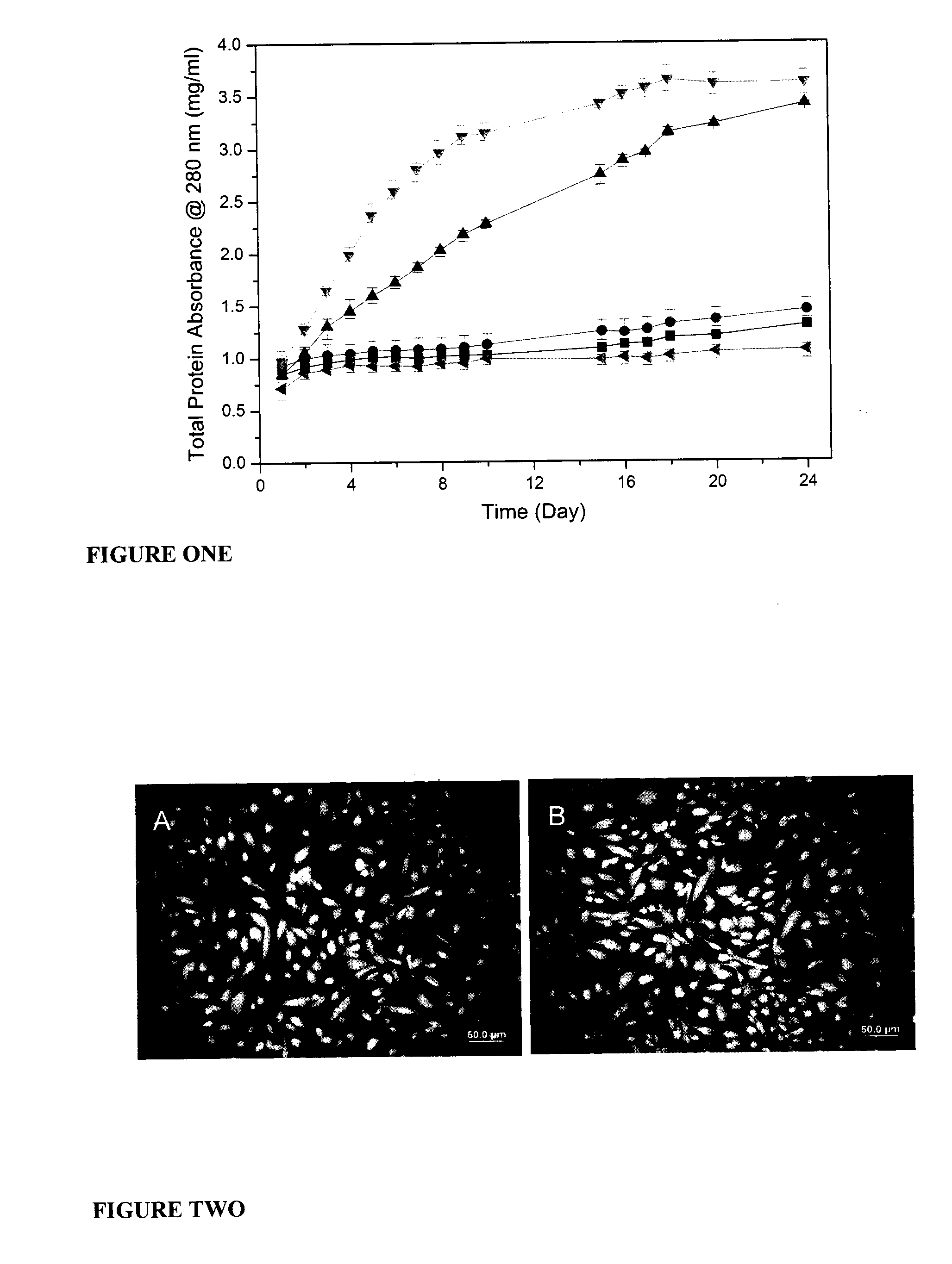
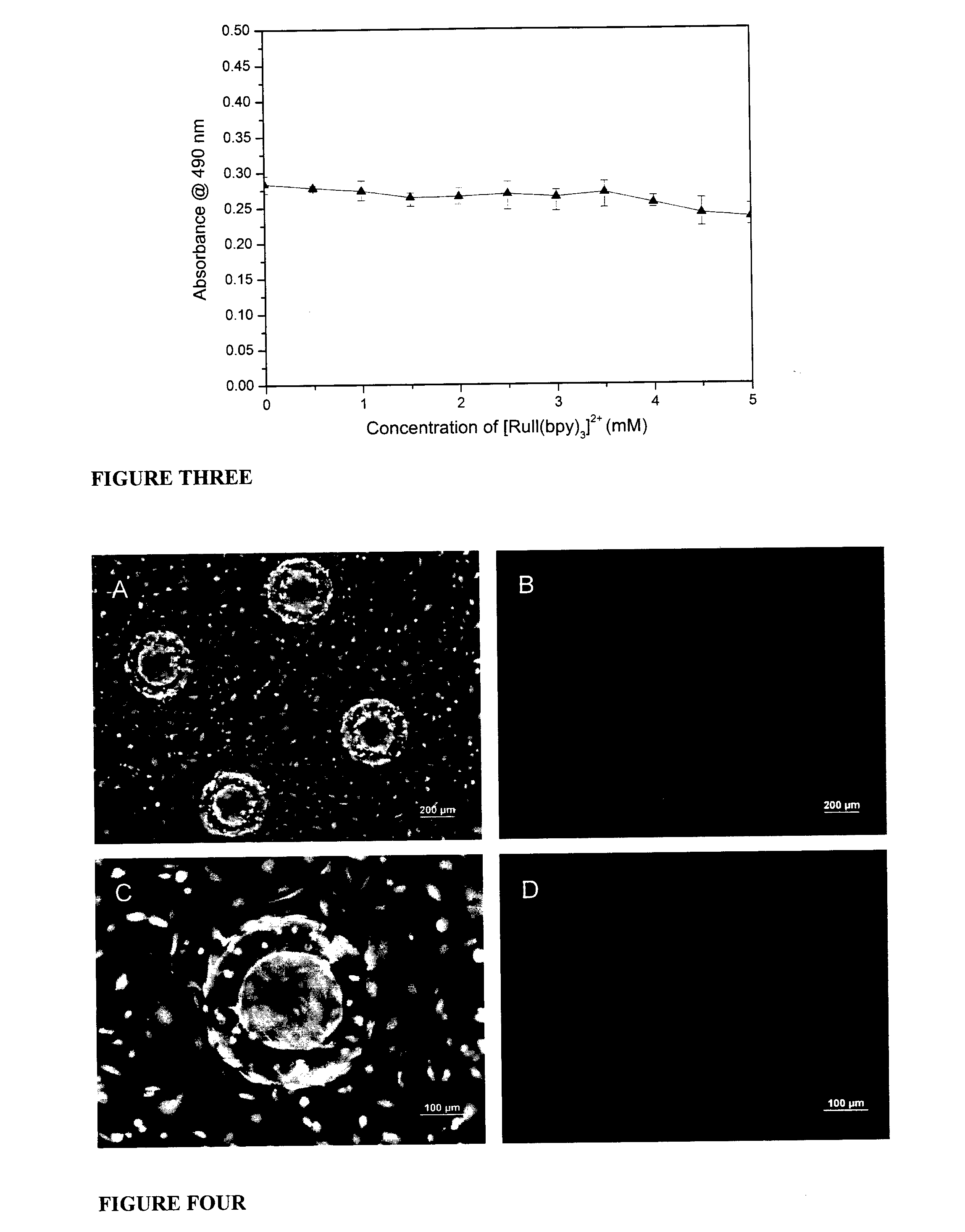
[0131]A photochemical cross-linking method was used to polymerize fibrinogen (see, method described in Elvin et al. (2004), “The development of photochemically crosslinked native fibrinogen as a rapidly formed and mechanically strong surgical tissue sealant”, Biomaterials, 25:2047-5). 15 mg of fibrinogen powder (bovine, Type 1-S; Sigma Aldrich) was weighed in a tube. Sodium persulfate (SPS) (Sigma Aldrich) was freshly prepared as a stock solution of 0.5 M in PBS. The photoinitiator, [Rull(bpy)3]2+ (Sigma Aldrich), was prepared as a stock solution of 50 mM in tissue culture grade water. 2 μl of SPS from the stock solution was then diluted to a final working solution of 10 mM by adding 100 μl of PBS solution. The entire volume of the working solution was added to 15 mg of fibrinog...

example 2

Preparation of Three-Dimensional Microstructured Tissue Scaffold with for Cell Seeding by Two-Photon Laser Scanning Photolithography

Materials and Methods

[0156]Fabrication of 3D Scaffolds by TPLSP

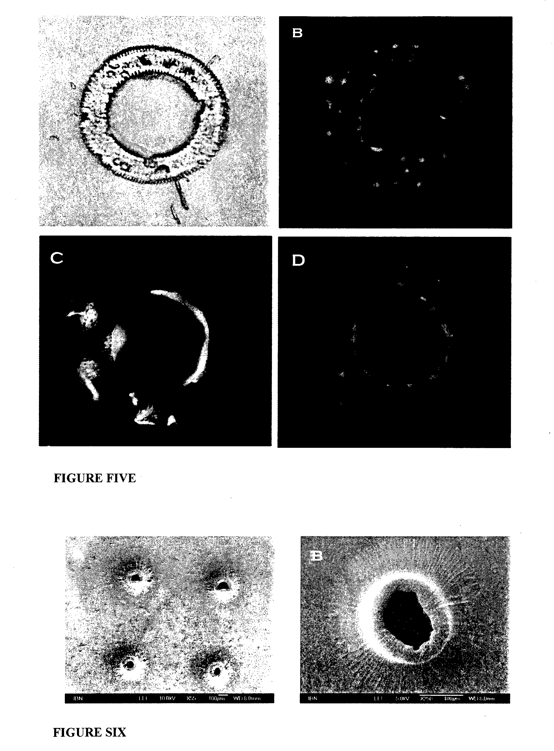
[0157]The photocurable polymer (Accura™ SI10) was obtained from 3D Systems (Rock Hill, S.C., USA). The desired scaffold was designed using CAD software (FIG. 9), and generated in a stereolithography system with a galvanometric mirror scanner (Scanlabs, Munich, Germany). An isolator was placed in front of the laser aperture to prevent reflected laser light from returning to the laser cavity. An acousto-optic modulator (AOM) served as a high-speed shutter for the system. The beam expander (Scanlabs, Munich, Germany) acted as the on-the-fly focusing module to automatically correct for any plane distortion. Axial control of the scanned structures was provided by a high-resolution elevation stage (Newport, Irvine, Calif., USA) that stepped with each slice of exposure. Localized polymerization wou...


PUM


Abstract

The present invention relates to a method for producing a three-dimensional scaffold construct comprising encapsulated cells, the method comprising: (a) providing a solution comprising cells, a photoinitiator, and a plurality of units capable of forming polymer chains; (b) providing a photolithography instrument comprising a two-photon laser; and (c) using the instrument to apply the laser to the solution to activate the photoinitiator thereby facilitating polymerisation of said units to form polymer chains, and, cross-linking of the polymer chains; wherein the laser is applied to the solution in three-dimensions in a pre-defined pattern to assemble said construct, and said cells are encapsulated within the assembled construct.

Description

INCORPORATION BY REFERENCE[0001]This application claims priority from U.S. provisional patent application No. 61 / 370,166 filed on 3 Aug. 2010, the entire contents of which are incorporated by reference in their entirety.TECHNICAL FIELD[0002]The invention relates generally to the field of tissue engineering. More specifically, the invention relates to microfabricated scaffold constructs and methods for their production.BACKGROUND[0003]Conventionally, three-dimensional (3D) structures are comprised of multiple layers of cells, obtained either by cell-sheet assembly or by cell-seeding onto a 3D polymer. The thick layers of cells deprive the inner layer of cells from the nutrients and oxygen needed for healthy growth. Even when the constructs are cultured on bioreactors, 100 μm or 4-7 cell layers are the maximum dimensions for a bioreactor to function efficiently (see, for example, Zandonella, (2003), “The beat goes on”, Nature; 421:884-86). In addition, there are other limitations that...

Claims


Application Information

Patent Timeline
IPC IPC(8): C12N5/00
CPCA61L27/54A61L27/56C12N5/0062A61L2300/62A61L27/58B33Y80/00
Inventor YING, JACKIE Y.HSIEH, TSENG-MINGWAN, ANDREW CHWEE AUN
Owner AGENCY FOR SCI TECH & RES
Why Eureka
Try Eureka