Nanowire-polymer composite electrodes

a technology of nanowires and composite electrodes, applied in the direction of sustainable manufacturing/processing, instruments, final product manufacturing, etc., can solve the problems of device failure, increasing the cost of the device fabrication process, and the flexibility and performance of the device in the electrode construct, etc., to achieve excellent optical transparency, electrical conductivity, surface smoothness

Active Publication Date: 2013-09-26
RGT UNIV OF CALIFORNIA
View PDF6 Cites 50 Cited by
  • Summary
  • Abstract
  • Description
  • Claims
  • Application Information

AI Technical Summary

Benefits of technology

[0016]The present invention provides methods for producing nanowire-polymer composite electrodes that are flexible, with excellent optical transparency, electrical conductivity, surface smoothnes...

Problems solved by technology
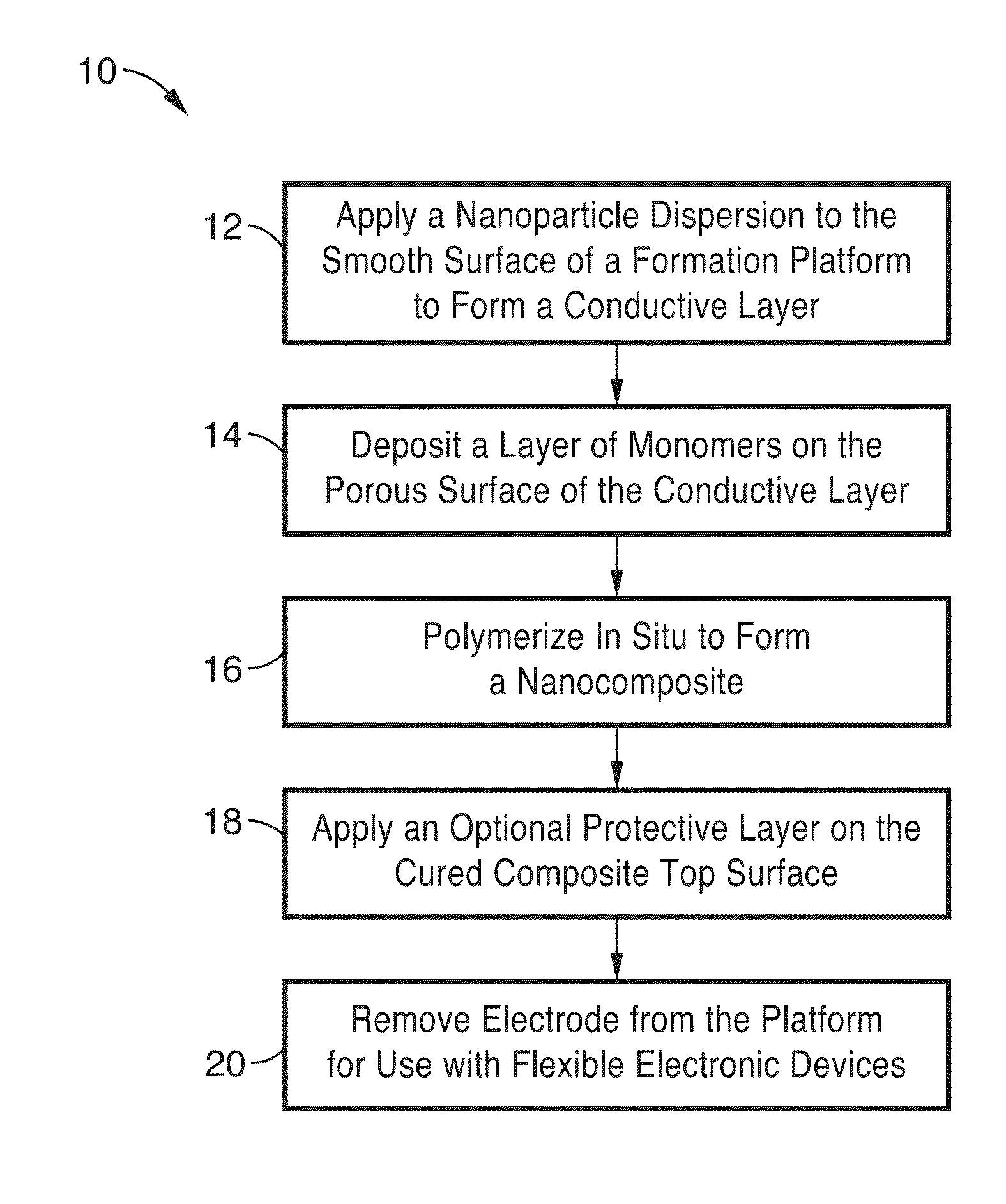
Any spikes on the electrode layer can cause an undesirable short circuit that leads to device failure.
However, device flexibility and performance are quite limited in these electrode constructs.
However, vapor deposition schemes require complicated equipment and a huge capital investment, greatly increasing the cost of the device fabrication process.
In addition, the materials available for use in such conventional vapor deposition processes are limited to mainly metal oxides or mixed metal oxides, such as indium-tin mixed oxide (ITO), antimony-tin mixed oxide (ATO), fluorine-doped tin oxide (FTO), and aluminum-doped zinc oxide (Al—ZO).
Although electrodes produced from these materials may be both transparent and m...

Method used


Image

  • Nanowire-polymer composite electrodes
  • Nanowire-polymer composite electrodes
  • Nanowire-polymer composite electrodes

Examples


example 1

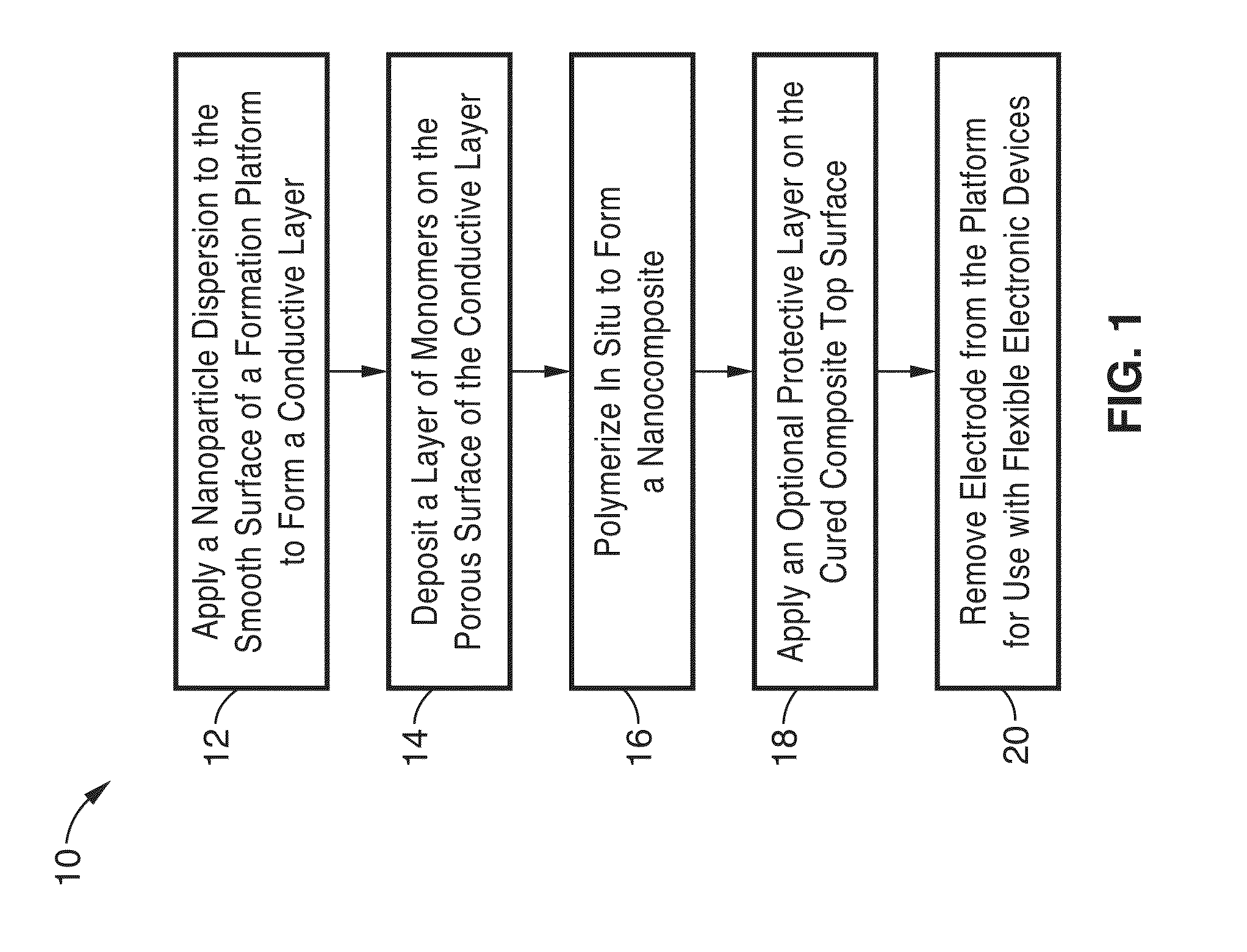
[0073]In order to demonstrate the invention, highly flexible silver nanowire (AgNW) electrodes on a cross-linked transparent polymethacrylate substrate were produced and evaluated. In this illustration, the flexibility of the AgNW electrodes was shown by bending up to 16% compressive strain with negligible change in sheet resistance. A 3.9X increase in sheet resistance was obtained at 16% tensile strain. The resistance change is recovered when the deformed electrode returns to its un-deformed shape. The AgNW / polymethacrylate electrodes that were produced were shown to have low surface resistance and high solvent resistivity together with strong adhesion and ultra-low surface smoothness.

[0074]The application of such electrode was demonstrated first in the fabrication of solution-processed PLEDs and compared with the device with commercial available ITO electrode. The efficacy of the PLEDs reached a maximum value of 14.0 cd / A, which was higher than the control devices using ITO anode....

example 2

[0080]The durability and conductivity of the AgNW electrode produced in Example 1 were evaluated. The AgNW / polymethacrylate electrode surface was subjected to repeatedly adhesive tape adhesion and peeling. No nanowires were apparently peeled off of the electrode surface. The sheet resistance was found to remain unchanged after 10 cycles of the Scotch tape test.

[0081]To compare the durability of the electrode with conventional films, two AgNW films were prepared: one by vacuum filtration and the other by a Meyer rod coating process. The first electrode film was made by vacuum filtration and transferred to plastic substrate by pressing the filter cake and lift off of the filter media. The sheet resistance-transmittance of electrode was 13Ω / sq and 85% transmittance at 550 nm. The second AgNW film that was formed by Meyer rod coating had a sheet resistance of 20Ω / sq and 87% transmittance at 550 nm. After scotch tape text, all AgNW layers were shown to be removed from both coatings. This...

example 3

[0084]Flexibility of AgNW electrode was also evaluated. Surface resistance change (R / R0) of the AgNW / polymer electrode with tensile and compressive strains are shown in FIG. 4. The inset of FIG. 4 shows the resistance change of an ITO / PET substrate upon tensile strain where the initial sheet resistance was 40Ω / sq.

[0085]The polymethacrylate film has a glass transition temperature (Tg) of 110° C. The network polymer imparts shape memory property to the AgNWs / polymethacrylate electrode. When heated to higher than 110° C., the electrodes could be stretched by up to 16% and bent to small curvature radii. Upon cooling to below 110° C., the deformed shape was “frozen.” The deformed electrodes relaxed from the temporary shape to the original ones when the deformed ones were heated to above Tg without the application of external tension or compression. Various temporary shapes were also created.

[0086]The resistance change of the AgNWs / polymethacrylate electrode was measured as a function of ...


PUM

PropertyMeasurementUnit
Temperatureaaaaaaaaaa
Thicknessaaaaaaaaaa
Heightaaaaaaaaaa

Abstract

A method for producing flexible, nanoparticle-polymer composite electrodes is described. Conductive nanoparticles, preferably metal nanowires or nanotubes, are deposited on a smooth surface of a platform to produce a porous conductive layer. A second application of conductive nanoparticles or a mixture of nanoparticles can also be deposited to form a porous conductive layer. The conductive layer is then coated with at least one coating of monomers that is polymerized to form a conductive layer-polymer composite film. Optionally, a protective coating can be applied to the top of the composite film. In one embodiment, the monomer coating includes light transducing particles to reduce the total internal reflection of light through the composite film or pigments that absorb light at one wavelength and re-emit light at a longer wavelength. The resulting composite film has an active side that is smooth with surface height variations of 100 nm or less.

Description

CROSS-REFERENCE TO RELATED APPLICATIONS[0001]This application is a 35 U.S.C. §111(a) continuation of PCT international application number PCT / US2011 / 053107 filed on Sep. 23, 2011, incorporated herein by reference in its entirety, which is a nonprovisional of U.S. provisional patent application Ser. No. 61 / 386,454 filed on Sep. 24, 2010, incorporated herein by reference in its entirety. Priority is claimed to each of the foregoing applications.[0002]The above-referenced PCT international application was published as PCT International Publication No. WO 2012 / 040637 on Mar. 29, 2012 and republished on May 31, 2012, and said publications are incorporated herein by reference in their entirety.STATEMENT REGARDING FEDERALLY SPONSORED RESEARCH OR DEVELOPMENT[0003]This invention was made with Government support under Grant No. DE-FC26-08NT01575, awarded by the United States Department of Energy. The Government has certain rights in this invention.INCORPORATION-BY-REFERENCE OF MATERIAL SUBMIT...

Claims


Application Information

Patent Timeline
IPC IPC(8): H01B1/22B29D11/00B29C41/00
CPCH01B1/02Y10T428/24355H01L51/003H01L51/5036H01L51/5206H01L51/5268H01L2227/326H01L2251/5338H01L2251/5369B29C41/003B29D11/0074H01B1/22G06F3/041G06F2203/04103H01L51/0021Y02E10/549Y02P70/50H10K71/60H10K71/80H10K50/125H10K50/81H10K50/854H10K59/1201H10K2102/331H10K2102/311
Inventor PEI, QIBINGYU, ZHIBIN
Owner RGT UNIV OF CALIFORNIA
Why Eureka
Try Eureka