Apparatus and Method for Treatment of In-Stent Restenosis

a technology of in-stent restenosis and apparatus, applied in the field of medical devices, systems and methods, can solve the problems of inability to achieve the effect of reducing the size of the vessel lumen, limiting the heating of the target tissue, and limiting the treatment options of the in-stent restenosis

Active Publication Date: 2013-10-24
BOSTON SCI SCIMED INC
View PDF10 Cites 180 Cited by
  • Summary
  • Abstract
  • Description
  • Claims
  • Application Information

AI Technical Summary

Benefits of technology

[0033]Tissue treatment may involve the application of energy, typically in the form of radiofrequency, microwave and/or ultrasound energy to electrodes. This energy will be controlled so as to limit a temperature of target and/or collateral tissues proximate to a luminal wall, for example, so as to limit the heating of an in-stent restenosis of the intimal layer of an artery structure. In some embodiments, the surface temperature range is from about 50° C. to about 90° C. For gentle heating, the surface temperature may range from about 50° C. to about 75° C., while for more aggressive heating, the surface temperature may range from about 75° C. to about 90° C. Limiting heating of a target tissue to

Problems solved by technology

Balloon angioplasty is often effective at opening a stenosed blood vessel, but the trauma associated with balloon dilation can impose significant injury, so that the benefits of balloon dilation may be limited in time.
The existing available options for treatment of in-stent restenosis may have limitations such as procedural complexity, constraints caused by the pre-existing implant, limitations in long-term efficacy, extremely high product development costs and protracted regulatory pathways, costly medication regimens, and the challenges of vascular biomechanics in places such as the leg.
None of the available interventional modalities provides optimal acute results, and long-term resu

Method used


Image

  • Apparatus and Method for Treatment of In-Stent Restenosis
  • Apparatus and Method for Treatment of In-Stent Restenosis
  • Apparatus and Method for Treatment of In-Stent Restenosis

Examples


Embodiment Construction

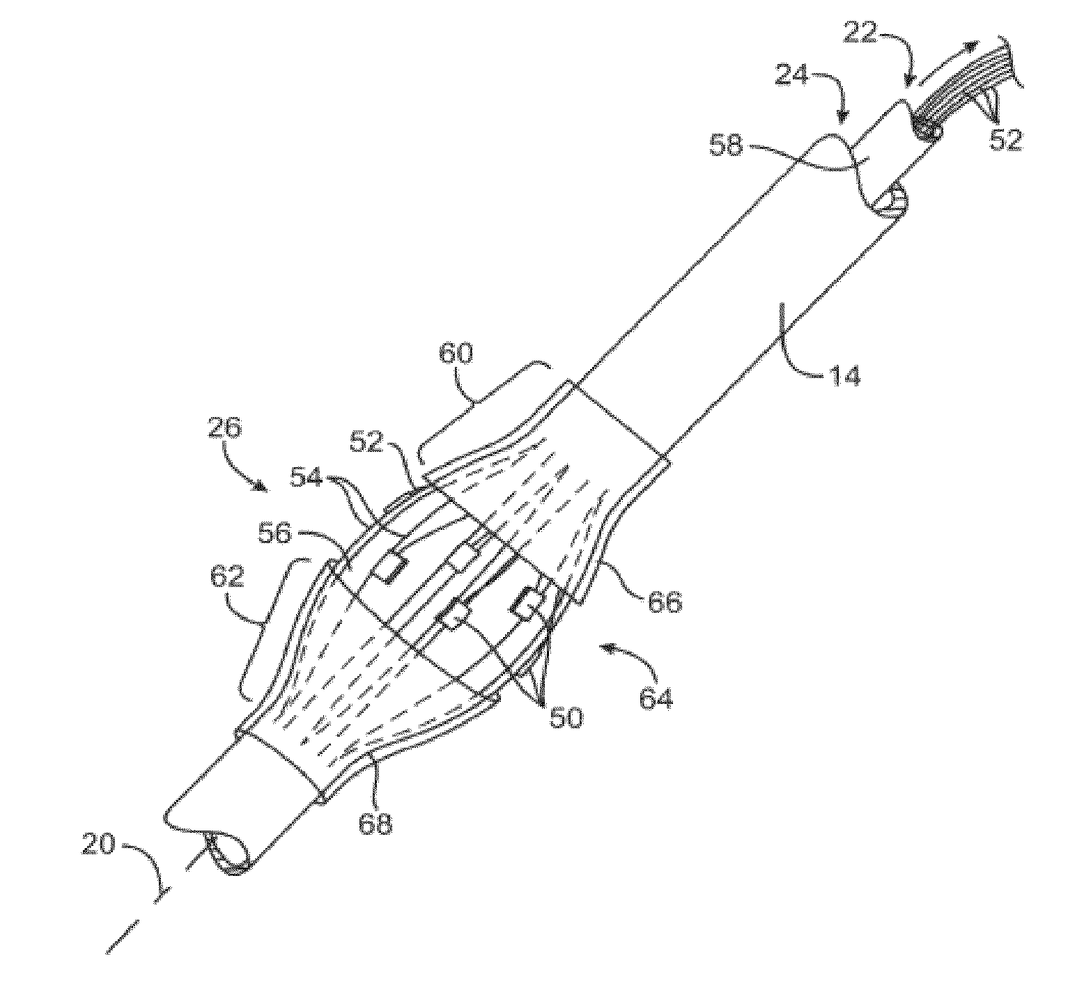
[0107]The present invention provides devices, systems, and methods to treat and / or analyze luminal tissue or tissues proximate to a lumen. The anatomical structure into which the catheter is placed may be, for example, the esophagus, the oral cavity, the nasopharyngeal cavity, the auditory tube and tympanic cavity, the sinus of the brain, the arterial system, the venous system, the heart, the larynx, the trachea, the bronchus, the stomach, the duodenum, the ileum, the colon, the rectum, the bladder, the kidney, the liver, the ureter, the ejaculatory duct, the vas deferens, the urethra, the uterine cavity, the vaginal canal, and the cervical canal. The invention will be particularly useful for characterizing and treating materials along an artery, such as to open the artery lumen and increase blood flow, further including stenosis developed as a result of prior stent implantation. Remodeling may involve the application of electrosurgical energy, typically in the form of radiofrequenc...


PUM


Abstract

A catheter and catheter system can use energy tailored for remodeling and/or removal of target material proximate to a body lumen, often of stenotic material or tissue in the luminal wall of a blood vessel of a patient. An elongate flexible catheter body with a radially expandable structure may have a plurality of electrodes or other electrosurgical energy delivery surfaces to radially engage the luminal wall when the structure expands. Feedback using one or parameters of voltage, current, power, temperature, impedance magnitude, impedance phase angle, and frequency may be used to selectively control the delivery of energy.

Description

CROSS-REFERENCES TO RELATED APPLICATIONS[0001]The present application claims the benefit under 35 USC 119(e) of U.S. Provisional Application No. 61 / 542,949 filed Oct. 4, 2011. The full disclosure of which is incorporated herein by reference in its entirety for all purposes.[0002]The present application is related to U.S. patent application Ser. No. 12 / 660,515 filed Feb. 26, 2010 (Allowed), entitled “Tuned RF Energy for Selective Treatment of Atheroma and Other Target Tissues”; U.S. patent application Ser. No. 11 / 392,231 filed Mar. 28, 2006 (now U.S. Pat. No. 7,742,795); entitled “Tuned RF Energy for Selective Treatment of Atheroma and Other Target Tissues, the full disclosures of which are incorporated herein by reference. The present application is related to U.S. patent application Ser. No. 10 / 938,138 filed on Sep. 10, 2004 (now U.S. Pat. No. 7,291,146), entitled “Selectable Eccentric Remodeling and / or Ablation of Atherosclerotic Material”; U.S. Provisional Application No. 60 / 852,...

Claims


Application Information

Patent Timeline
IPC IPC(8): A61N5/00
CPCA61N5/00A61B18/1492A61B2018/00267A61B2018/00404A61B2018/00779A61B2018/00791A61B2018/00827A61B2018/00875A61B2018/00892A61B2018/124A61B2018/1467A61N5/0601A61N2005/0602
Inventor MATHUR, PRABODHMAZOR, MEITALPEREZ, DOLORES
Owner BOSTON SCI SCIMED INC
Why Eureka
Try Eureka