
Reversible solid adsorption method and system utilizing waste heat for on-board recovery and storage of co2 from motor vehicle internal combustion engine exhaust gases

a technology of waste heat and solid adsorption method, which is applied in the direction of gas treatment, mechanical equipment, inorganic chemistry, etc., can solve the problems of lack of any economies of scale, space and weight limitations, and carbon dioxide management from mobile sources, so as to reduce co2 emissions, maximize fuel energy values, and waste heat high to moderate temperature

Active Publication Date: 2013-11-14
SAUDI ARABIAN OIL CO
View PDF24 Cites 27 Cited by
  • Summary
  • Abstract
  • Description
  • Claims
  • Application Information

AI Technical Summary

Benefits of technology

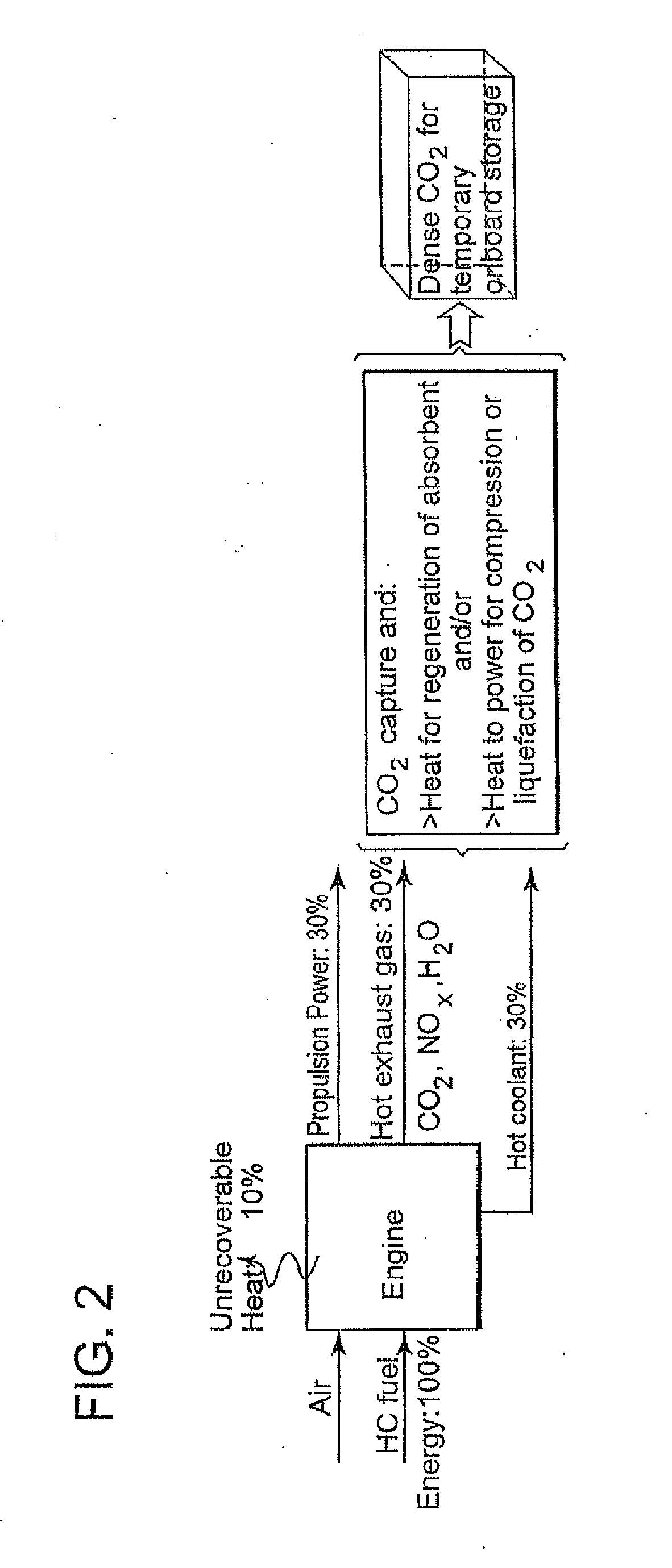
This invention is a method to capture and increase the density of CO2 from an engine's exhaust gases using waste heat that is available on board the vehicle. The method includes an adsorption separation method, a recovery of pure CO2 and regeneration of the capture agent, the conversion of engine waste heat into power, and the use of this power to increase the density of captured CO2 for temporary on-board storage. This method reduces the cost and volume requirement for temporary on-board storage of the CO2. The invention is also superior to prior art methods because it uses readily available high-temperature waste heat.

Problems solved by technology

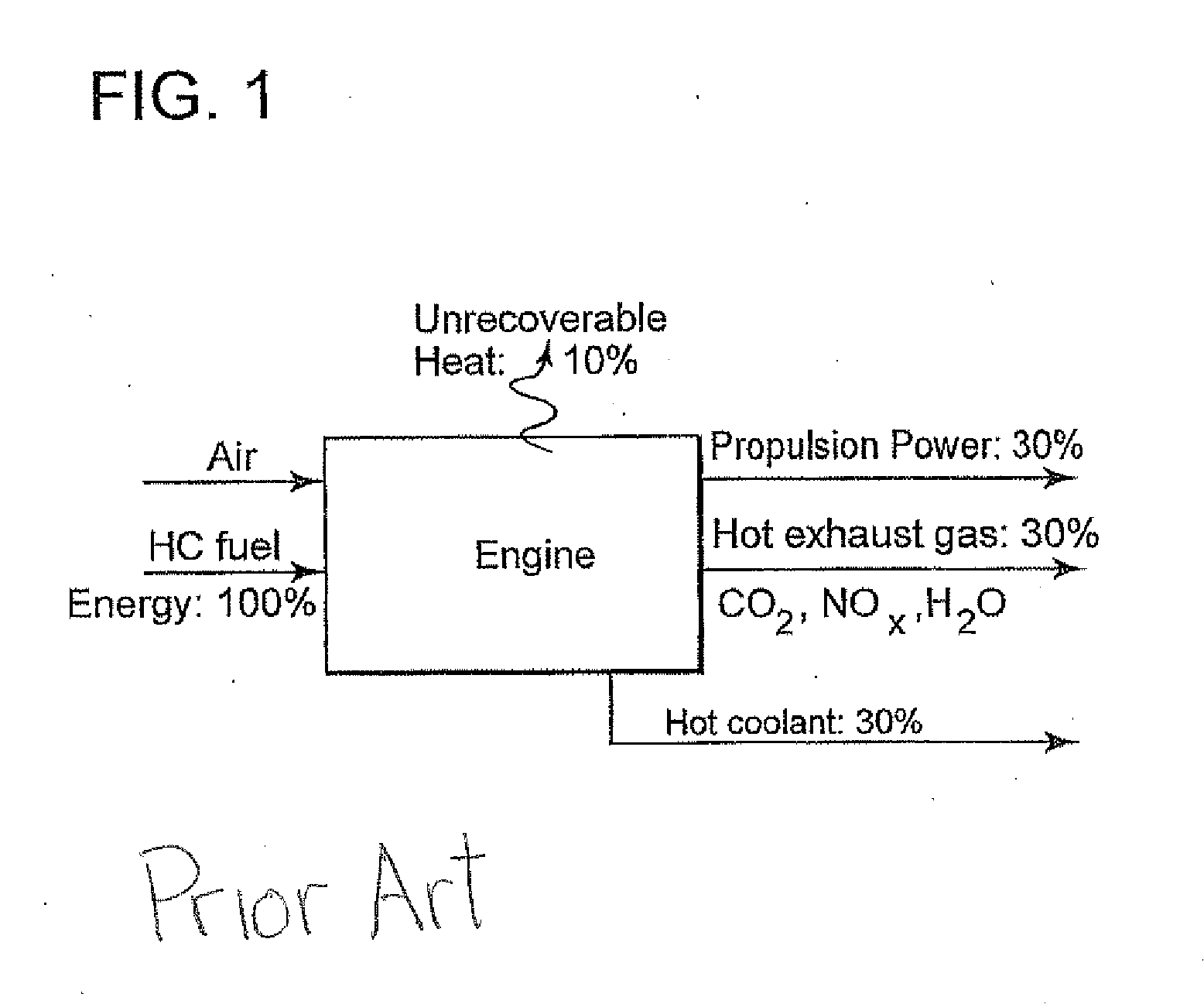
Carbon dioxide management from mobile sources has many challenges including space and weight limitations, the lack of any economies of scale and the dynamic nature of the operation of the ICE powering the mobile sources.
Those that address the problem of reducing CO2 emissions from mobile sources employ either combustion using oxygen, provide no means for the regeneration and reuse of the CO2 capture agent, and / or make no use of waste heat recovered from the hot source.
Combustion using oxygen requires oxygen-nitrogen separation which is more energy-intensive than separating CO2 from the exhaust gases and would be more difficult if attempted on board the vehicle.
The focus of CO2 capture technology being on stationary, or fixed sources, the capture of CO2 from mobile sources has generally been considered too expensive, since it involves a distributed system with a reverse economy of scale.
The solution to the problem has appeared to be impractical due to on-board vehicle space limitations, the additional energy and apparatus requirements and the dynamic nature of the vehicle's operating cycle, e.g., intermittent periods of rapid acceleration and deceleration.

Method used


Image

  • Reversible solid adsorption method and system utilizing waste heat for on-board recovery and storage of co2 from motor vehicle internal combustion engine exhaust gases
  • Reversible solid adsorption method and system utilizing waste heat for on-board recovery and storage of co2 from motor vehicle internal combustion engine exhaust gases
  • Reversible solid adsorption method and system utilizing waste heat for on-board recovery and storage of co2 from motor vehicle internal combustion engine exhaust gases

Examples


example 1

[0109]This example describes the preparation of a solid CO2 sorbent for use in the process of the invention by what is referred to as a gelatin process. An amount (395 g) of magnesium carbonate hydroxide (MgCO3.Mg(OH)2×H2O) was added to 800 ml of a solution of sodium carbonate (42.18 g) and sodium nitrate (21.63 g) dissolved in deionized water. This produced a mixed salt slurry which was stirred for 30 minutes. The slurry was then covered and allowed to sit for 16 hours at ambient temperature, after which it was dried at 120° C. for 16 hours to form a dry cake of MgO:Na2CO3:NaNO3. Analysis showed a mass ratio of 75.8:16:8.2 and a molar ratio of Mg:Na of about 4.8. This dry cake was then calcined by heating from 120° C. to 450° C., at a ramp rate of 3° C. / minute, followed by 450° C. for 4 hours. The calcined cake was crushed and sieved to collect a 150-425 mesh fraction, which is suitable for use in a packed bed with an inert material such as SiC to occupy any remaining volume. Test ...

example 2

[0110]This example describes preparation of a solid CO2 sorbent of the same mixed salt composition for use in invention by what is referred to as a precipitation process. A solution of 233.4 g of Na2CO3 in 3000 ml deionized water was placed in a 5.0 liter plastic beaker, and stirred vigorously with a mechanical agitator. A second solution, of 188.4 g Mg(NO3)2: 6 H2O in 500 ml of deionized water, was pumped into the first solution, at a rate of approximately 30 ml / minute. A slurry resulted which was stirred for an hour. The slurry was stored, overnight, as described supra, and then filtered to yield a wet precipitate cake. About 3200 mls of filtrate were collected. This was dried, at 120° C. for 24 hours to form a dry cake, which was treated a described in Example 1. Test results indicated that the amount of CO2 loaded on the sorbent reached its peak at 325° C., and as with the sorbent from Example 1, the sorbent product from this example was also effective over a wide temperature ra...


PUM

PropertyMeasurementUnit
Fractionaaaaaaaaaa
Temperatureaaaaaaaaaa
Pressureaaaaaaaaaa

Abstract

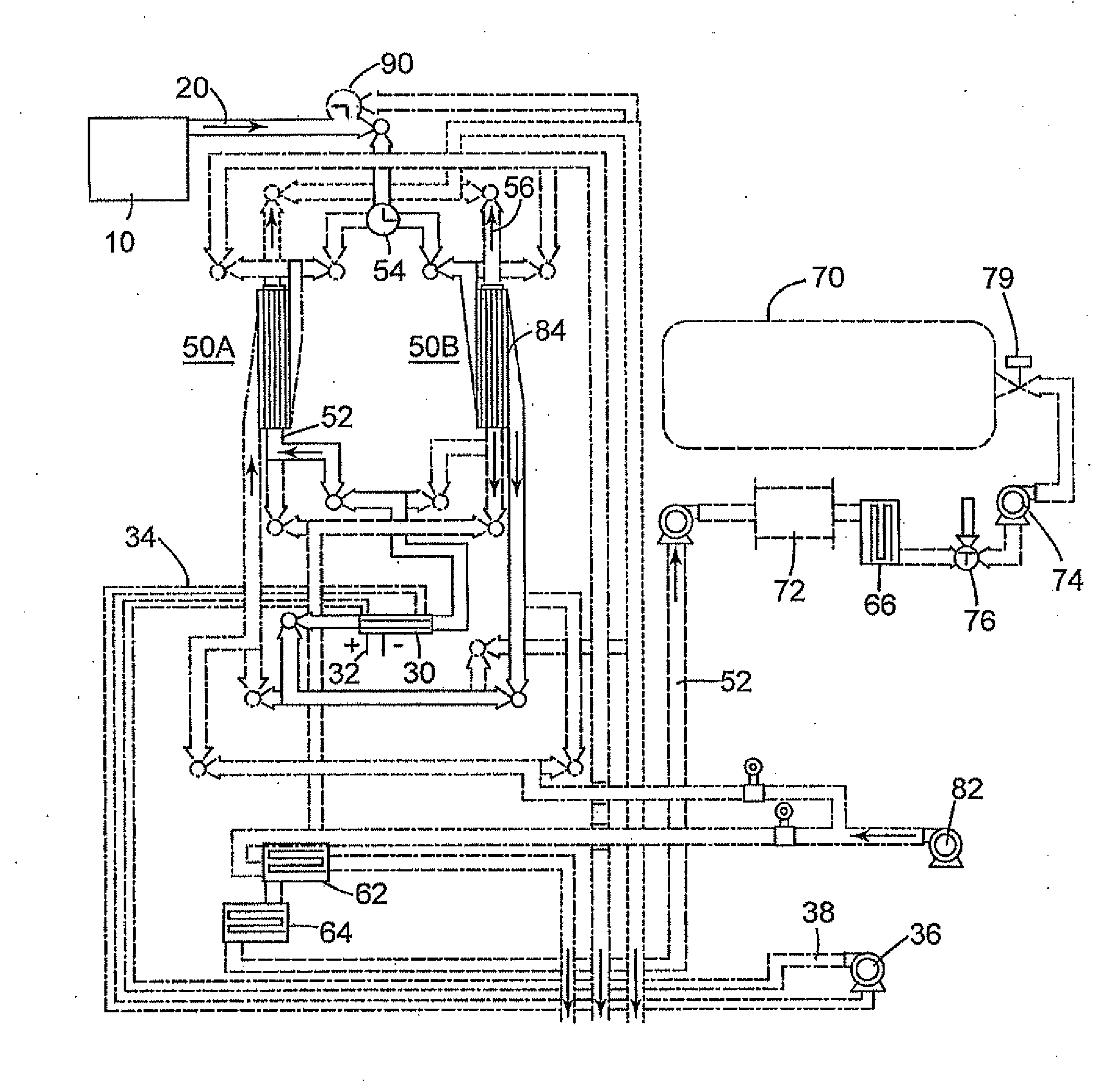
A method and system are described for on-board treatment of an exhaust stream containing CO2 emitted by a hydrocarbon-fueled internal combustion engine (ICE) used to power a vehicle in order to reduce the amount of CO2 discharged into the atmosphere which include:a. a treatment zone on board the vehicle containing a capture agent having a predetermined capacity for extracting CO2 from the exhaust stream,the treatment zone preferably operating in swing mode with at least two subsystems, each having an inlet for admitting the exhaust gas stream and an outlet for passage of a treated exhaust stream having a reduced CO2 content,the treatment zone preferably operating in swing mode with at least two subsystems, each including a heat exchanger with an inlet for receiving the hot exhaust gas stream from the ICE for passage in heat exchange relation with the capture agent to release CO2 and regenerate the capture agent, and an outlet for the cooled exhaust gas stream,the treatment zone having a CO2 discharge outlet for CO2 released from the regenerated capture agent;b. a compression zone in fluid communication with the CO2 discharge outlet from the treatment zone, the compression zone including one or more compressors for reducing the volume of the CO2;c. a storage zone for receiving the compressed CO2 for temporary storage on board the vehicle; andd. an exhaust gas conduit in fluid communication with the treated exhaust gas stream outlet from the treatment zone.

Description

FIELD OF THE INVENTION[0001]The invention relates to the reduction of carbon dioxide emissions from the exhaust gas stream of vehicles powered by internal combustion engines and other heat engines that produce waste heat.BACKGROUND OF THE INVENTION[0002]The currently accepted thinking is that global warming is due to emissions of greenhouse gases such as carbon dioxide (CO2) and methane (CH4). About a quarter of global human-originated CO2 emissions are currently estimated to come from mobile sources, i.e., automobiles, trucks, buses and trains that are powered by an internal combustion engine (ICE). This proportional contribution is likely to grow rapidly in the foreseeable future with the projected surge in automobile and truck ownership in developing countries. At present, the transportation sector is a major market for crude oil, and controlling CO2 emissions is both an environmental responsibility and a desirable goal in order to maintain the viability of the crude oil market i...

Claims


Application Information

Patent Timeline
IPC IPC(8): F01N3/00C01B32/50
CPCF01N3/00B01D53/0462B01D53/62B01D53/92B01D2251/304B01D2251/402B01D2257/504B01D2259/65Y02P20/129Y02C20/40B01D53/02B01D53/14
Inventor HAMAD, ESAM ZAKIAL-SADAT, WAJDI ISSAM
Owner SAUDI ARABIAN OIL CO
Learn More