Previously-known methods and apparatus typically involve use of multiple catheters and devices to accomplish such treatments, which adds time, cost and complexity, increased
exposure to
ionizing radiation and risk of morbidity to previously-known therapeutic procedures.
However, use of these conventional
percutaneous treatments has an important limitation:
restenosis—the exuberant proliferation of
smooth muscle cells that grow to re-occlude the treated vessel segment, causing the reoccurrence of symptoms and necessitating potential reintervention.
The latter technology has been demonstrated to significantly reduce coronary
artery restenosis when compared to
angioplasty or
bare metal stents, however, its use requires chronic administration of adjunct pharmacotherapies to prevent subacute
stent thrombosis, the sudden and life threatening clotting of the
stent.
Unfortunately, not all patients tolerate these essential pharmacotherapies due to impaired tolerance, allergic reactions or
contraindication to such
drug use (i.e., history of previous bleeding) and / or their associated expense.
ISR poses additional risk to the patient by necessitating additional vessel reintervention to re-establish vessel
blood flow.
Currently, there is no established treatment for the vexing problem of ISR, which occurs in about 30%-50% of nitinol stents over a 1-2 year follow-up period, a rate that may increase depending on the patient demographic (i.e., diabetics) and vessel morphology (
small vessel diameter, length of diseased vessel treated and the presence of vessel wall
calcification).
Importantly, there are presently no recognized effective and durable therapies to treat ISR; as such,
emerging technologies focus on preventing restenosis through the application of anti-restenotic therapeutic agents into the diseased vessel wall
layers via the vessel's luminal surface.
All of the previously-known systems described in the foregoing patents have had drawbacks that have prevented commercialization of those designs.
For example, catheters having a single apertured balloon, such as described in the above patent to Shaffer et al., cannot provide uniform distribution of a
drug or other material around the circumference or along the axis of the vessel due to jetting through the apertures.
Catheters with apertured protrusions, such as described in the above patents to Barath et al. and Vigil et al, are difficult to manufacture and are believed to be prone to having the apertures clogged with debris when the balloon is embedded into the plaque lining the vessel wall.
Also, the use of excessively high pressures within the balloon to clear the apertured protrusions may lead to excessively non-uniform
drug infusion and potential vessel
dissection.
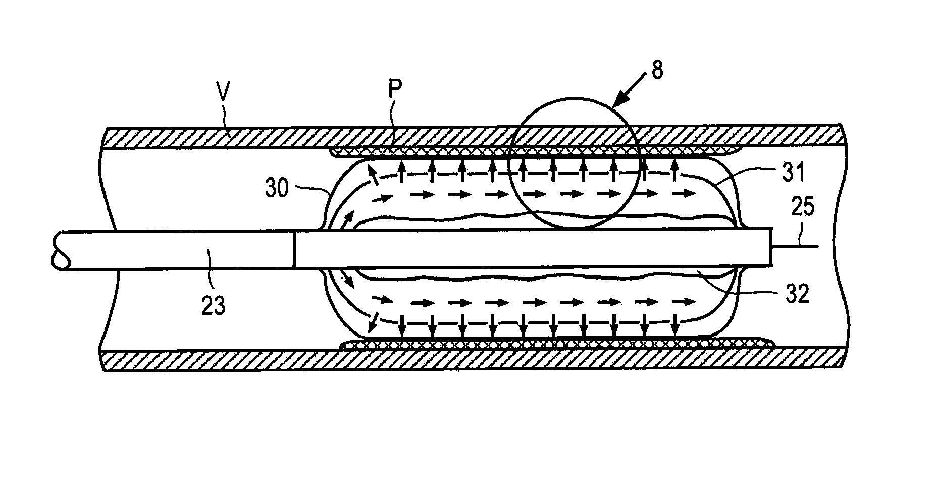
However, as the Abiuso catheter lacks an inner impermeable balloon to move the drug infusing
layers into
apposition with the vessel wall, there is the potential for much of the drug to be washed into
systemic circulation during deployment of the nested balloons.
Specifically, the presence of dense fibro-calcific and calcified intimal and medial plaques, are associated with peri-procedural failure (due to vessel
recoil and / or vessel wall
dissection) and subsequent restenosis as these plaques are effective barriers to the penetration and uptake of therapeutic drugs delivered luminally.
A drawback of these systems, however, is that each forms a new mechanical structure disposed within the vessel that is separate and distinct from the vessel wall.
Because the arteries, and to a lesser extent, the veins, expand and contract during each
cardiac cycle due to pressure pulsations, such attempts to form a rigid mechanical support that is not integrated with the vessel wall are inherently problematic.

