
Transparent vapor-deposited film

Active Publication Date: 2015-10-01
DAI NIPPON PRINTING CO LTD
View PDF3 Cites 6 Cited by
  • Summary
  • Abstract
  • Description
  • Claims
  • Application Information

AI Technical Summary

Benefits of technology

The invention is a highly adhesive transparent vapor-deposited film that can be used on plastic substrates. It is made up of aluminum oxide and formed using a special plasma preprocessing device that has a limited gap and increases the adhesiveness between the plastic substrate and the vapor-deposited film. The vapor-deposited film contains a large amount of Al—C covalent bonds, which are formed by the plasma preprocessing device on the substrate surface and reinforce the adhesiveness. The film also has excellent transparency, bonding strength, and water-resistant adhesiveness, compared to prior art methods. By controlling the formation of Al—C covalent bonds and modifying the plasma ion implantation effect, the adhesiveness can be further improved and the film can be made with reduced damage to the substrate. Overall, the invention provides a highly effective and transparent vapor-deposited film that is suitable for use on plastic substrates.

Problems solved by technology

Typical materials that have been proposed are aluminum foil or metal aluminum vapor-deposited films, that are largely unaffected by temperature or humidity, and although these exhibit highly stable gas barrier properties, when they are incinerated as waste after use, they are poorly suited for incineration and are not easy to dispose of after use, while another problem is that they have low transparency.
However, because polyvinylidene chloride-based resins contain chlorine in the structure, when they are incinerated as waste after use they generate harmful chlorine gas, which is undesirable from the viewpoint of environmental sanitation.
It is therefore necessary at the current time to employ a complex layered structure of an ethylene-vinyl alcohol copolymer as a substrate with a barrier property, in order to block water vapor, and this tends to increase production cost.
However, plastic substrates that are easily affected by temperature and humidity easily undergo dimensional change, and therefore an inorganic oxide vapor-deposited film layer such as a transparent silicon oxide thin-film layer or aluminum oxide vapor deposition layer that is formed thereover cannot easily follow the expansion and contraction that takes place with dimensional change of the plastic substrate.
Consequently, the phenomenon of interlayer separation often occurs between the plastic substrate and the inorganic oxide vapor-deposited film layer such as a transparent silicon oxide thin-film layer or silicon oxide vapor deposition layer in high temperature, high humidity environments and the like, and cracking or generation of pinholes can also occur.
As a result, the original barrier performance is significantly lost, and it is extremely difficult to retain barrier performance.
However, when adhesiveness is produced by hydrogen bonding with hydroxyl groups, the adhesiveness is notably reduced in the high temperature, high humidity environments required for electronic device use, such as in the case of electronic paper, because of destruction of the hydrogen bonds.
Furthermore, since plasma processing merely passes the film under a plasma atmosphere generated in air, it is currently not possible to achieve sufficient adhesiveness between substrates and vapor-deposited films.
Furthermore, the undercoat treatment method described in PTL 2 is usually carried out by providing an undercoat layer as an adhesive layer on the plastic film surface, and this increases cost due to a greater number of steps during the production process.
However, since RIE methods introduce functional groups onto the plastic substrate, the resistance to cold water and hot water that can cause hydrolysis at the interface has still remained insufficient.
An Ed value at or above a certain value using the same method can be achieved by increasing the plasma density or lengthening the processing time, but increasing the plasma density requires a high output power source, which can increase damage to the substrate, while lengthening the processing time can lower productivity (see PTL 4 and Patent Publication 5).
Furthermore, the following problems may arise, depending on the film-forming method used in combination with the preprocessing.
In vacuum vapor deposition methods, the thin-film formation speed is not slow, but the precision of thin-film homogeneity is poor, leading to poor yields.
In sputtering, despite satisfactory precision of thin-film homogeneity, the thin-film forming rate is very low and productivity is poor.
In thermal CVD processes, a source gas is oxidized and decomposed by the heat energy of the substrate to form a thin-film, and they require the substrate to be at high temperature, and when the substrate is a plastic film, decomposition and oxidation of the plastic film can occur, making it impossible to form a homogeneous thin-film on the plastic substrate.
In methods of forming a vapor-deposited film on a plastic substrate that has been subjected to preprocessing by conventional preprocessing means, problems have arisen such as insufficiency of the barrier property of the inorganic oxide vapor-deposited film formed on the plastic substrate, even if the substrate with a gas barrier property previously had resistance to moist heat, or problems such as insufficiency of adhesiveness between the vapor-deposited film and the plastic substrate.
Also, when a vapor-deposited film is formed by a film forming device combined with the aforementioned preprocessing, formation of the vapor-deposited film is accomplished in a continuous manner but without uniform formation of the vapor-deposited film, and attempts to maintain adhesiveness have resulted in a slower vapor-deposited film-forming speed and lower productivity.
In addition, when using conventional vapor-deposited films there has been limited success in obtaining sufficient resistance to moist heat while maintaining adhesiveness.

Method used


Image

  • Transparent vapor-deposited film
  • Transparent vapor-deposited film
  • Transparent vapor-deposited film

Examples


example 1

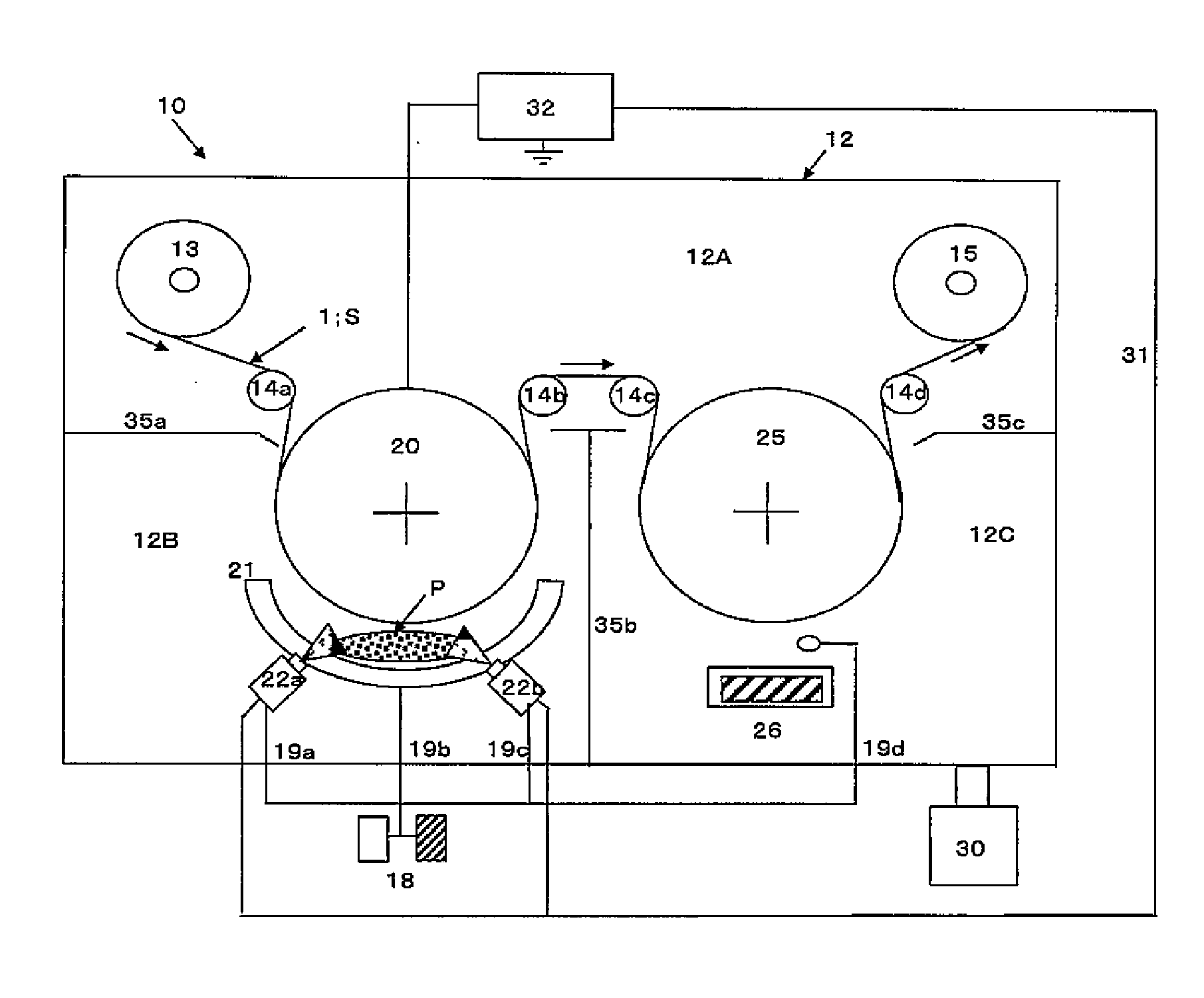
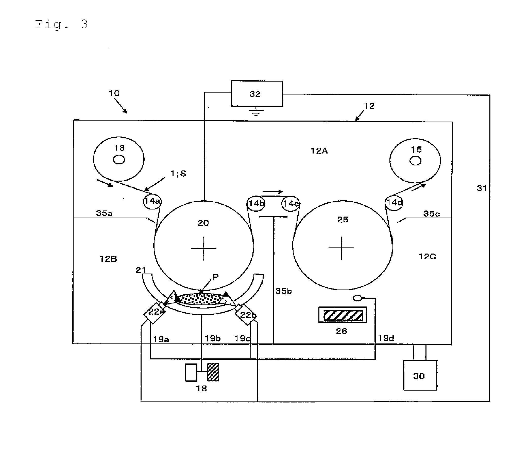
[0225]On the side of a 12 μm-thick PET (PET-F, product of Unitika, Ltd.) substrate to be provided with a vapor deposition layer, plasma was introduced using a continuous vapor-deposited film forming device having a separated preprocessing chamber provided with a plasma preprocessing device of the invention, and a film-forming chamber, from a plasma supply nozzle in the preprocessing chamber under the following plasma conditions, and after conducting plasma preprocessing at a transport speed of 480 m / min, an aluminum oxide vapor deposition layer was formed to a thickness of 8 nm on the plasma-treated surface under the following conditions being continuously transported in the film-forming chamber, using a reactive resistance heating system as the heating means of the vacuum vapor deposition method.

(Plasma Preprocessing Conditions)

[0226]High-frequency power source output: 4 kW

Plasma strength: 550 W·sec / m2

Plasma-forming gas: Oxygen 100 (sccm), argon 1000 (sccm)

magnetism forming means:...

example 2

[0228]On the side of a 12 μm-thick PET (PET-F, product of Unitika, Ltd.) substrate to be provided with a vapor deposition layer, plasma was introduced from a plasma supply nozzle under the same conditions an Example 1, except that the plasma strength was 12 kW in the preprocessing chamber of the continuous vapor-deposited film forming device having a separated preprocessing chamber provided with a plasma preprocessing device of the invention, and a film-forming chamber, and after conducting plasma preprocessing at a transport speed of 480 m / min, an aluminum oxide vapor deposition layer was formed to a thickness of 8 nm on the plasma-treated surface under the same conditions as Example 1, being continuously transported in the film-forming chamber, using a reactive resistance heating system.

example 3

[0229]On the side of a 12 μm-thick PET (PET-F, product of Unitika, Ltd.) substrate to be provided with a vapor deposition layer, plasma was introduced from a plasma supply nozzle under the same conditions an Example 1, except that the plasma strength was 12 kW in the preprocessing chamber of the continuous vapor-deposited film forming device having a separated preprocessing chamber, provided with a plasma preprocessing device of the invention, and a film-forming chamber, and the oxygen plasma-forming gas was changed to nitrogen, and after conducting plasma preprocessing at a transport speed of 480 m / min, an aluminum oxide vapor deposition layer was formed to a thickness of 8 nm on the plasma-treated surface under the same conditions as Example 1 while being continuously transported in the film-forming chamber, using a reactive resistance heating system.


PUM

PropertyMeasurementUnit
Temperatureaaaaaaaaaa
Fractionaaaaaaaaaa

Abstract

Employed is a roller-type continuous vapor-deposited film forming device in which a film-forming section and a preprocessing section provided with a plasma preprocessing device are arranged in series at a distance from each other. With a substrate transported at a high speed, plasma (P) is supplied to the substrate surface side while set to an electrically positive potential by a plasma preprocessing means for supplying the plasma toward the substrate (S) in a space enclosed in a preprocessing roller, and enclosed in a plasma supply means for supplying a plasma-forming gas and in a magnet (21), which is a magnetism formation means. An active preprocessed surface is formed on the surface of the substrate (S). An inorganic oxide vapor-deposited film having as a principal component thereof an aluminum oxide containing AL-C covalent bonds is immediately formed at high speed in succession on the preprocessed surface of the substrate to produce a highly adhesive transparent vapor-deposited film.

Description

TECHNICAL FIELD[0001]The present invention relates to a vapor-deposited film having a transparent property, and to a packaging material using the same.[0002]More specifically, it relates to a transparent vapor-deposited film having transparency and high adhesiveness, and reinforced adhesiveness with plastic substrates and inorganic oxide vapor-deposited films composed mainly of aluminum oxide, which is suitable for use as a packaging material to be used for packaging in a wide range of fields including foods and retort foods, drugs and electronic parts, as well as to a packaging material using the same.BACKGROUND ART[0003]As wrapping materials for filling and packing of foods and beverages, chemical products, sundry goods and the like in the prior art, there have been developed substrates with gas barrier properties in a variety of forms that block or shield the passage of oxygen gas, water vapor and the like, in order to prevent alteration or discoloration of the contents.[0004]Typ...

Claims


Application Information

Patent Timeline
IPC IPC(8): C23C14/08C23C14/02B32B7/12
CPCC23C14/081B32B7/12C23C14/021B32B2307/412B32B2439/00B32B2307/31B32B2307/7242B32B2255/20C23C14/562Y10T428/24843Y10T428/265Y10T428/2826
Inventor MATSUI, SHIGEKIASUMA, TATSUOKOMURO, TERUHISAMIYAMA, HIROSHIGOTO, TAKAKAZUMIYAZAKI, KAORUMATSUZAKI, HIROSHI
Owner DAI NIPPON PRINTING CO LTD
Features
  • Generate Ideas
  • Intellectual Property
  • Life Sciences
  • Materials
  • Tech Scout
  • Unparalleled Data Quality
  • Higher Quality Content
  • 60% Fewer Hallucinations
Learn More