Ultra-short pulse mid-ir mode-locked laser

a mode-locked laser and ultra-short pulse technology, applied in the direction of laser details, active medium materials, optical resonator shape and construction, etc., can solve the problems of incident light attenuation incident light attenuation,

Inactive Publication Date: 2016-10-06
IPG PHOTONICS CORP
View PDF4 Cites 15 Cited by
  • Summary
  • Abstract
  • Description
  • Claims
  • Application Information

AI Technical Summary

Problems solved by technology

These optically phase-locked modes then interfere with each other to form short optical pulses.
In a linear regime, where the incident optical intensity is weak, the saturable absorber absorbs the incident light resulting in attenuation of the optical intensity of the incident light.
When the incident optical intensity is raised to a higher level, the saturation of absorption occurs and the absorption by the saturable absorber decreases which leads to a decrease in attenuation of the optical intensity of the incident light.
The SESAM requires complex and costly fabrication systems.
It further may require an expensive hermetic packaging for a long-term environmental stability and may not withstand high optical powers.
Also, at strong focusing, the undesirable multi-pulse operation regime may be observed possibly due to the two-photon absorption in the SESAM.
Currently, high quality TM:II-VI single crystal materials are not readily available.
Crystal sublimation during the growth process results in poor uniformity of the single-crystal samples and limits the dopant concentration.
Hence, considering the cost and often questionable quality of TM:II-VI laser materials in single crystals, even a possibility of mass production of this type of lasers was given little or no consideration.
KLM lasers usually exhibit difficulties with starting the mode-locked regime: after turning on, the laser emits continuous-wave radiation, and the emission of short pulses can be started only with an external intervention, e.g. by knocking or moving an optical component of the laser.
The necessity of a mechanical intervention for starting the mode locked regime is impractical.
However, at that time the industry did not have sufficiently sophisticated measuring equipment that could reliably confirm the mode-locked laser regime, the short pulse duration and the sustainability of the KLM.

Method used


Image

  • Ultra-short pulse mid-ir mode-locked laser
  • Ultra-short pulse mid-ir mode-locked laser
  • Ultra-short pulse mid-ir mode-locked laser

Examples


Embodiment Construction

[0043]Reference will now be made in detail to embodiments of the invention. Wherever possible, same or similar numerals are used in the drawings and the description to refer to the same or like parts or steps. The drawings are in simplified form and are not to precise scale. Unless specifically noted, it is intended that the words and phrases in the specification and claims be given the ordinary and accustomed meaning to those of ordinary skill in the fiber laser arts. The word “couple” and similar terms do not necessarily denote direct and immediate connections, but also include mechanical optical connections through free space or intermediate elements.

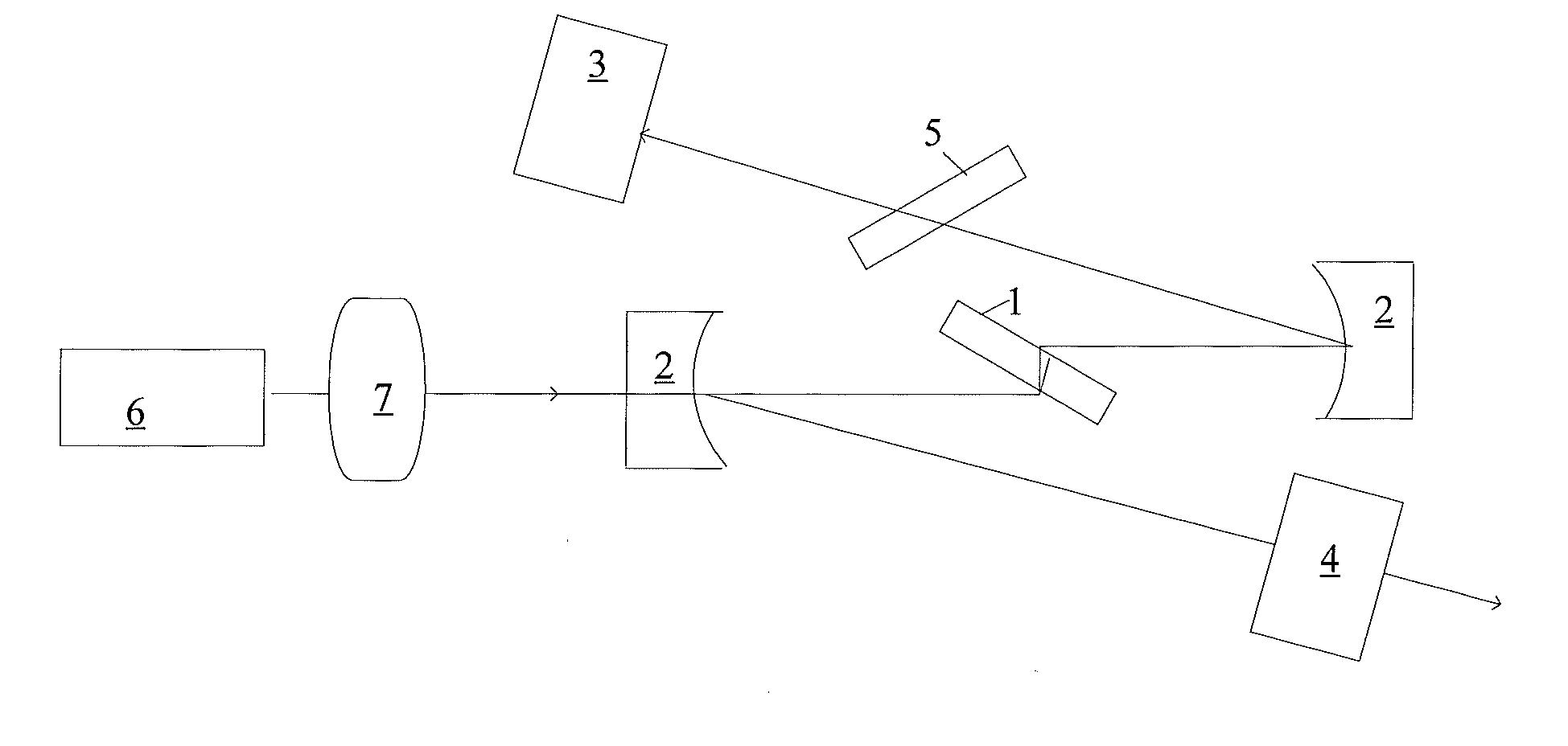
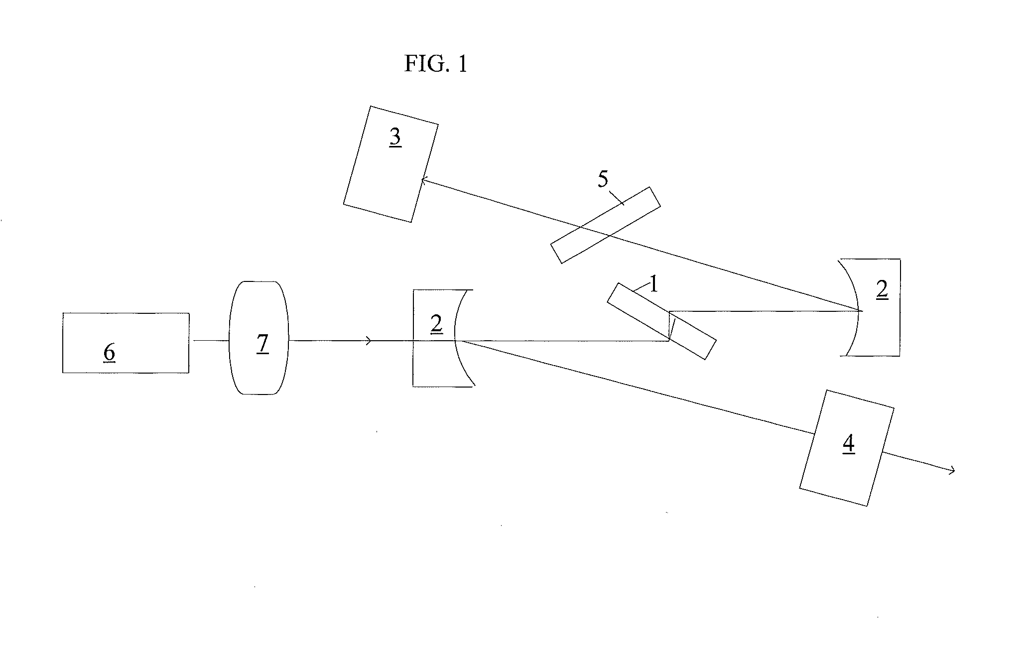
[0044]FIG. 1 illustrates rather one of many known configurations of the laser cavity (or resonator) for generating ultra-short pulses in a mid-IR spectral range known as a Z-shaped cavity. While the number of reflective elements may vary, the invariable part of it includes a gain element 1 placed inside the resonator. The laser cavit...


PUM


Abstract

A short-pulse mode-locked laser is configured with at least two reflective elements defining a resonant cavity therebetween, a laser gain element (“GE”) placed inside the resonant cavity at normal incidence and selected from transition metal doped II-VI materials; and an optical pump emitting pulsed output to synchronously or quasi-synchronously pump the GE at a pulse repetition rate frequency fpump, the pump being configured so that the fpump substantially matches an inversed round trip time in the resonant cavity flaser:fpump≈flaser=c/2L, where c is the speed of light, L is the length of the resonant cavity. The synchronous or quasi-synchronous pumping triggers and sustains a short-pulse emission of the laser with picosecond or femtosecond pulse durations.

Description

SUMMARY OF THE DISCLOSURE[0001]1. Field of The Invention[0002]The present invention relates generally to a gain media configured with II-VI chalcogenides which are doped with transition metals (“TM:II-VI”). More particularly, the disclosure relates to mid-IR solid state mode locked lasers and optical amplifiers all based on TM:II-VI gain media and operative to emit picosecond and femtosecond pulses in a 1.8-8 μm spectral range.[0003]2. Prior Art Discussion[0004]Pulsed lasers have a great potential for applications in various fields, such as optical signal processing, laser surgery, bio-medicine, optical diagnostics, two-photon microscopy, optical probing, optical reflectometry, laser spectroscopy, material processing, etc. There are two main classes of pulsed lasers, namely Q-switched lasers and mode-locked lasers with the latter being of a particular interest for this disclosure.[0005]Mode-locked lasers can produce ultra-short optical pulses at high repetition rates. As is known in...

Claims


Application Information

Patent Timeline
Patent Type & Authority Applications(United States)
IPC IPC(8): H01S3/094H01S3/08H01S3/081H01S3/00H01S3/13H01S3/16H01S3/06
CPCH01S3/094026H01S3/1628H01S3/162H01S3/0815H01S3/0612H01S3/0014H01S3/1305H01S3/08004H01S3/1112H01S3/1623H01S3/0816H01S3/2308H01S3/1095H01S3/1685
Inventor VASILYEV, SERGEYMIROV, MICHAELGAPONTSEV, VALENTIN
Owner IPG PHOTONICS CORP
Why Eureka
Try Eureka