

Dielectric waveguide line
a technology of dielectric waveguides and waveguide lines, which is applied in the direction of waveguides, waveguide type devices, instruments, etc., can solve the problems of high attenuation, too high attenuation to transmit millimeter waves and submillimeters, and always occur in cables that transmit high-frequency signals. , to achieve the effect of low loss tangent, high permittivity and low loss tangen
- Summary
- Abstract
- Description
- Claims
- Application Information
AI Technical Summary
Benefits of technology
Problems solved by technology
Method used
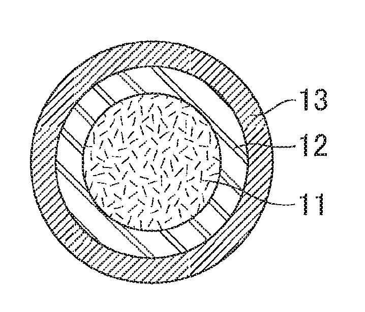
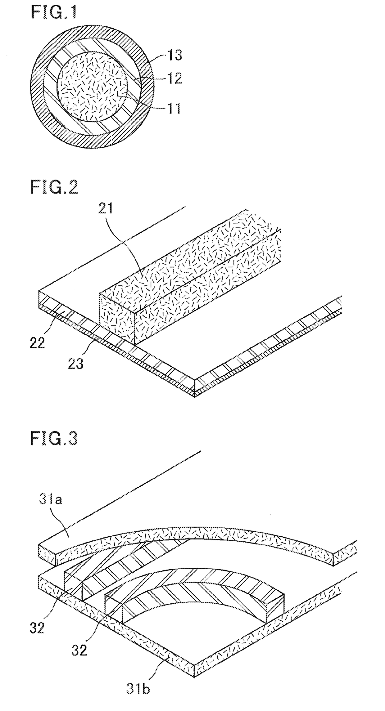
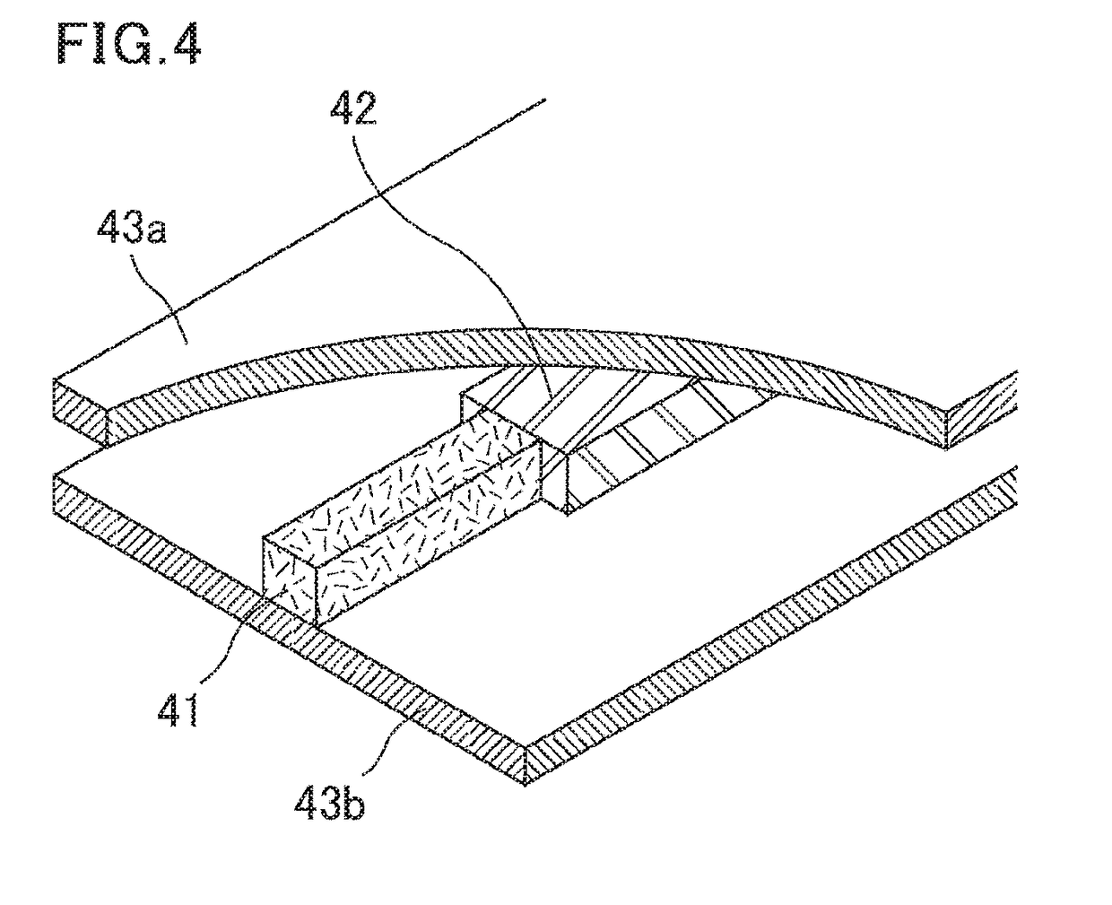
Image

Examples
examples
[0129]The present invention is described with reference to experiments. The experiments, however, are not intended to limit the scope of the present invention.
[0130]The numerical values in the experiments were measured by the following respective methods.
Permittivity and Loss Tangent (Tan δ)
[0131]The permittivity and loss tangent (tan δ) of a cylindrical PTFE molded article, tubular PTFE molded article, or stretched PTFE porous tube were measured by a cavity resonator (2.45 GHz) available from Kanto Electronic Application and Development Inc.
[0132]The permittivity and loss tangent (tan δ) of a flat-plate-shaped PTFE molded article or stretched PTFE porous film were measured in accordance with “Microwave measurement of complex permittivity of dielectric plate materials”, Prof. Kobayashi (Saitama University), MW87-7.
[0133]The hardness was measured by a spring-type hardness meter (JIS-A shaped) defined in JIS K6301-1975.
[0134]The specific gravity was measured by...
experiment 1
[0135]PTFE fine powder (2 kg) whose standard specific gravity (SSG) is 2.175 was mixed with a hydrocarbon-based solvent (400 g), whereby a PTFE paste was prepared.
[0136]The PTFE paste was molded by paste extrusion molding using a φ2.0 mm extrusion die to obtain a cylindrical unsintered PTFE molded article (A). The obtained PTFE molded article (A) was placed in a hot air circulating electric furnace. The temperature was gradually increased from 100° C. to 250° C. to remove the hydrocarbon-based solvent by evaporation. Thereby, a cylindrical PTFE molded article (B) was obtained.
[0137]The obtained cylindrical PTFE molded article (B) was placed in a salt bath (molten salt, 1:1 mixture of potassium nitrate and sodium nitrate) and heated, so that a cylindrical. PTFE molded article (C) was obtained. The diameter of the heated cylindrical PTFE molded article was 2.95 mm. The heating temperature, heating duration, and the results of heating are shown in Table 1.
experiment 3
[0139]A dried cylindrical PTFE molded article (B) was obtained by the same procedure as that in Experiment 1. The dried cylindrical PTFE molded article (B) was placed in a hot air circulating electric furnace and heated. The heating temperature, heating duration, and the results of heating are shown in Table 1.
PUM
| Property | Measurement | Unit |
|---|---|---|
| porosity | aaaaa | aaaaa |
| porosity | aaaaa | aaaaa |
| frequency | aaaaa | aaaaa |
Abstract
Description
Claims
Application Information