
Process for Flexible and Shape-Conformal Rope-Shape Supercapacitors

a supercapacitor and flexible technology, applied in the field of supercapacitors or ultracapacitors, can solve the problems of low apparent densities of active materials, low actual mass loading of electrodes, and severe constraints on the adaptability or feasibility of being implemented in confined spaces, so as to achieve maximum contact or interfacial areas

Active Publication Date: 2018-08-16
NANOTEK INSTR GRP LLC
View PDF0 Cites 19 Cited by
  • Summary
  • Abstract
  • Description
  • Claims
  • Application Information

AI Technical Summary

Benefits of technology

The invention is a supercapacitor that has a porous separator around the second electrode to protect it. The first and second electrodes are pre-impregnated with an active material and electrolyte mixture and are braided together to form a braid or twist yarn. The two electrodes are packed closely together to maximize the contact areas between them. The technical benefit of this invention is that it provides a way to enhance the performance and reliability of supercapacitors by improving the stability of the electrodes and minimizing the size of the electrodes.

Problems solved by technology

Conventional supercapacitors and batteries (e.g. 18650-type cylindrical cells, rectangular pouch cells, and prismatic cells) are mechanically rigid and this non-flexibility feature has severely constrained their adaptability or feasibility of being implemented in confined spaces or for use in wearable devices.
However, there are Several Serious Technical Issues Associated with Current State-of-the-Art ECs or Supercapacitors:(1) Experience with ECs based on activated carbon electrodes shows that the experimentally measured capacitance is always much lower than the geometrical capacitance calculated from the measured surface area and the width of the dipole layer.
This disappointing performance is related to the presence of micro-pores (<2 nm, mostly <1 nm) and ascribed to inaccessibility of some pores by the electrolyte, wetting deficiencies, and / or the inability of a double layer to form successfully in pores in which the oppositely charged surfaces are less than about 1-2 nm apart.
In activated carbons, depending on the source of the carbon and the heat treatment temperature, a surprising amount of surfaces can be in the form of such micro-pores.(2) Despite the high gravimetric capacitances at the electrode level (based on active material weights alone) as frequently claimed in open literature and patent documents, these electrodes unfortunately fail to provide energy storage devices with high capacities at the supercapacitor cell or pack level (based on the total cell weight or pack weight).
This is due to the notion that, in these reports, the actual mass loadings of the electrodes and the apparent densities for the active materials are too low.
The low mass loading is primarily due to the inability to obtain thicker electrodes (thicker than 100-200 μm) using the conventional slurry coating procedure.
Contrarily, thicker samples tend to become extremely brittle or of poor structural integrity and would also require the use of large amounts of binder resin.
These problems are particularly acute for graphene material-based electrodes.
It has not been previously possible to produce graphene-based electrodes that are thicker than 150 μm and remain highly porous with pores remaining fully accessible to liquid electrolyte.
The low areal densities and low volume densities (related to thin electrodes and poor packing density) result in relatively low volumetric capacitances and low volumetric energy density of the supercapacitor cells.

Method used


Image

  • Process for Flexible and Shape-Conformal Rope-Shape Supercapacitors
  • Process for Flexible and Shape-Conformal Rope-Shape Supercapacitors
  • Process for Flexible and Shape-Conformal Rope-Shape Supercapacitors

Examples


example 1

Illustrative Examples of Electronically Conductive Porous Rods or Filaments as a Porous Current Collector to Accommodate an Active Material-electrolyte Mixture

[0174]Various types of metal foams, carbon foams, and fine metal webs are commercially available for use as conductive porous rods (serving as a current collector) in an anode or cathode; e.g. Ni foam, Cu foam, Al foam, Ti foam, Ni mesh / web, stainless steel fiber mesh, etc. Metal-coated polymer foams and carbon foams can also be used as current collectors. For making macroscopic rope-shaped flexible and shape-conformable supercapacitors, the most desirable thickness / diameter ranges for these conductive porous rods are 50-1000 μm, preferably 100-800 μm, more preferably 200-600 μm. For making microscopic rope-shape supercapacitors (having a diameter from 100 nm to 100 μm, for instance), graphene foams, graphene aerogel foam, porous carbon fibers (e.g. made by electro-spinning polymer fibers, carbonizing the polymer fibers, and a...

example 2

Ni foam and CVD Graphene Foam-based Porous Rods Supported on Ni Foam Templates

[0175]The procedure for producing CVD graphene foam was adapted from that disclosed in open literature: Chen, Z. et al. “Three-dimensional flexible and conductive interconnected graphene networks grown by chemical vapor deposition,” Nature Materials, 10, 424-428 (2011). Nickel foam, a porous structure with an interconnected 3D scaffold of nickel was chosen as a template for the growth of graphene foam. Briefly, carbon was introduced into a nickel foam by decomposing CH4 at 1,000° C. under ambient pressure, and graphene films were then deposited on the surface of the nickel foam. Due to the difference in the thermal expansion coefficients between nickel and graphene, ripples and wrinkles were formed on the graphene films. Four types of foams made in this example were used as a current collector in the presently invented lithium batteries: Ni foam, CVD graphene-coated Ni form, CVD graphene foam (Ni being etc...

example 3

Graphitic Foam-Based Conductive Porous Rods from Pitch-Based Carbon Foams

[0180]Pitch powder, granules, or pellets are placed in a aluminum mold with the desired final shape of the foam. Mitsubishi ARA-24 meso-phase pitch was utilized. The sample is evacuated to less than 1 torr and then heated to a temperature approximately 300° C. At this point, the vacuum was released to a nitrogen blanket and then a pressure of up to 1,000 psi was applied. The temperature of the system was then raised to 800° C. This was performed at a rate of 2 degree C / min. The temperature was held for at least 15 minutes to achieve a soak and then the furnace power was turned off and cooled to room temperature at a rate of approximately 1.5 degree C / min with release of pressure at a rate of approximately 2 psi / min. Final foam temperatures were 630° C. and 800° C. During the cooling cycle, pressure is released gradually to atmospheric conditions. The foam was then heat treated to 1050° C. (carbonized) under a n...


PUM

PropertyMeasurementUnit
specific surface areaaaaaaaaaaa
widthaaaaaaaaaa
length/diameter aspect ratioaaaaaaaaaa

Abstract

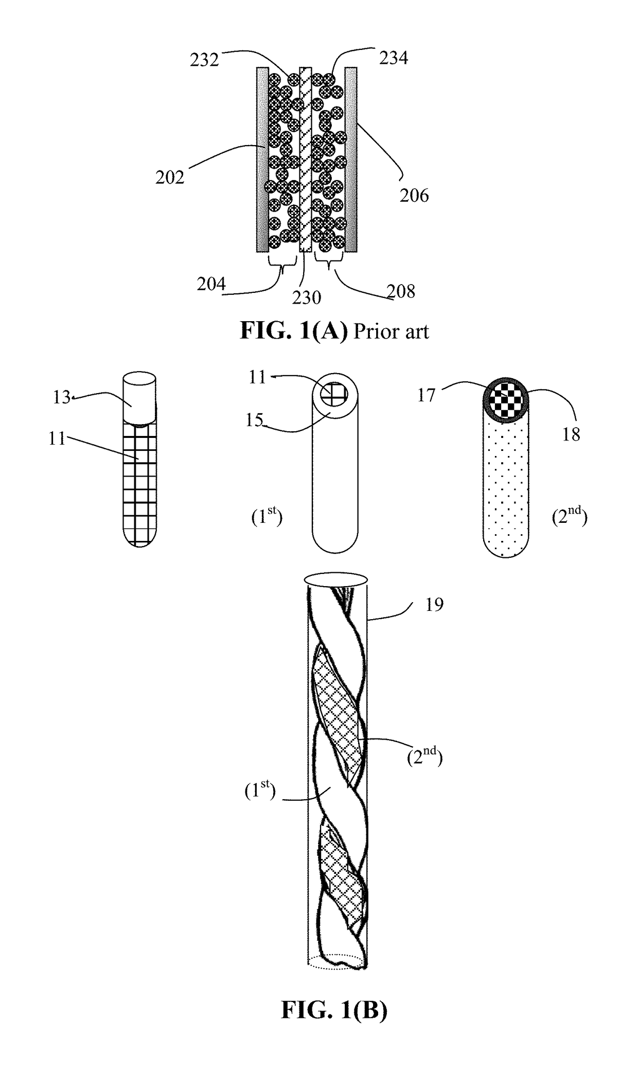
Provided is a process for producing a rope-shaped supercapacitor comprising: (a) impregnating a first mixture of a first electrode active material (e.g. activated carbon or isolated graphene sheets) and a first electrolyte into pores of a first porous rod to form a first electrode; (b) encasing a porous separator around the first electrode to form a separator-protected first electrode; (c) impregnating a second mixture of a second electrode active material and a second electrolyte into pores of a second conductive porous rod to form a second electrode; (d) combining the separator-protected first electrode and second electrode form a braid or twist yarn; and (e) wrapping or encasing a protective sheath around the braid or yarn to form the supercapacitor.

Description

FIELD OF THE INVENTION[0001]The present invention relates generally to the field of supercapacitors or ultracapacitors, and more particularly to the rope-shape supercapacitors that are flexible and shape-conformal.BACKGROUND OF THE INVENTION[0002]Conventional supercapacitors and batteries (e.g. 18650-type cylindrical cells, rectangular pouch cells, and prismatic cells) are mechanically rigid and this non-flexibility feature has severely constrained their adaptability or feasibility of being implemented in confined spaces or for use in wearable devices. Flexible and shape-conformable power sources can be used to overcome these design limitations. These new power sources will enable the development of next-generation electronic devices, such as smart mobile gadgets, roll-up displays, wearable devices, and biomedical sensors. Flexible and conformable power sources will also save weight and space in electric vehicles.[0003]Electrochemical capacitors (ECs), also known as ultracapacitors ...

Claims


Application Information

Patent Timeline
Patent Type & Authority Applications(United States)
IPC IPC(8): H01G11/06H01G11/50H01G11/48H01G11/46H01G11/42H01G11/36H01G11/26H01G11/24H01G11/74H01G11/52H01G11/58H01G11/84
CPCH01G11/06H01G11/50H01G11/48H01G11/46H01G11/42H01G11/36H01G11/26H01G11/24H01G11/74H01G11/52H01G11/58H01G11/84Y02E60/13H01G9/0029H01G9/04
Inventor ZHAMU, ARUNAJANG, BOR Z.
Owner NANOTEK INSTR GRP LLC
Learn More