Scanning ir sensor for gas safety and emissions monitoring

a gas safety and emission monitoring technology, applied in the direction of optical radiation measurement, instruments, spectrometry/spectrophotometry/monochromators, etc., can solve the problems of requiring direct sampling in place, affecting the safety and environmental of the gas, and reducing the coverage of the gas, so as to achieve the effect of less expensive, more reliable and cost-effectiv

Active Publication Date: 2018-09-20
MULTISENSOR SCI INC
View PDF2 Cites 38 Cited by
  • Summary
  • Abstract
  • Description
  • Claims
  • Application Information

AI Technical Summary

Benefits of technology

[0018]This invention has several key advantages over thermal infrared gas imaging sensors that operate in the mid-wave or long-wave infrared parts of the spectrum. This includes the ability to detect and quantify leaked gas with no temperature difference relative to the background, as the invention utilizes short-wave infrared light provided by natural sunlight or by lamps of appropriate color temperature, and does not rely on a thermal contrast between gas and the background or a background of varying temperature. The detectors suitable for use in this invention do not require cryogenic cooling, using instead thermo-electric cooling that is more reliable and less expensive than cryogenic coolers such as a Stirling engine or liquid nitrogen. The invention can also detect gas leaks in the presence of humid air, steam and fog, as the hydrocarbon features detected in the SWIR do not overlap spectral regions where water vapor absorption is significant, which is a major shortcoming for gas imagers operating in other parts of the infrared spectrum. The embodiment of a scan imager provides a cost-effective design, by allowing the use of a small number of discrete photo-diodes or small photodiode array. This approach trades away video-rate imaging for cost-effective but slower image scanning, which is satisfactory for numerous applications. Finally, the use of a rapid scanning device enables site-wide monitoring for gas leaks with a response time quick enough for safety applications (approximately 10 second response time). Many flexible scan patterns can be implemented and rapidly switched between in an automated fashion. This invention documents several examples of scan patterns to detect, localize and image leaks. These examples are meant to be illustrative but not exhaustive. Yet the concept and advantages should be clear. This enables the invention to be useful for gas safety, leak detection and repair, and gas emissions monitoring applications.

Problems solved by technology

Natural gas leaks create both safety and environmental hazards, and occur along the entire gas supply chain from the well to the street (so-called upstream, midstream, and downstream sectors).
Other hydrocarbons found in natural gas, as well vapors emanating from liquids separated from gas and oil include ethane, propane, butane, pentane, hexane, octane, and heavier hydrocarbons, which form volatile organic compounds that generate smog which is a health hazard.
They can be fixed in place for continuous monitoring, or hand portable for inspections, but they require direct sampling in place and provide very limited coverage.
They may provide concentration measurements, but do not provide leak rate estimates.
These sensors detect gas present anywhere along the line between the light emitter and the photo-detector (or between combined emitter / detector assembly and a remote reflector if the optical path is folded), but they cannot determine where along the path the gas is, nor from where it came, and has limited coverage to only the narrow open path between emitter and detector.
By utilizing multiple wavelengths of light, such sensors can measure column density of gas along the open path, but cannot measure or estimate concentration nor leak rate.
The leading commercially available gas imaging sensors operate in only a single narrow band of the mid-wave infrared spectrum, and do not provide quantitative data, only pictures to be interpreted by the human operator.
Such systems have proven to be both expensive and have significant shortcomings.
This requires that the background and gas differ in temperature by at least several degrees Celsius, otherwise the light absorbed (or emitted) by the gas will not provide sufficient signal contrast to be reliably detected by the human operators of these thermal sensors.
Thus, there is little or no thermal contrast between the gas and the ground, and so cannot be reliably detected by a thermal infrared sensor.
Another major shortcoming of mid-wave and long-wave gas imaging sensors is their poor performance in the presence of water vapor (high humidity, steam), fog and light rain.
Thus, water vapor will mask the presence of a methane leak, and conversely, water vapor will trigger a false alarm for methane.
Additionally, all mid-wave infrared and some long-wave infrared gas imaging sensors require cryogenic cooling, which is both expensive and unreliable.
Finally, none of the available gas imaging sensors provides a capability to estimate leak rate from a hole, or emission flux from a surface.

Method used


Image

  • Scanning ir sensor for gas safety and emissions monitoring
  • Scanning ir sensor for gas safety and emissions monitoring
  • Scanning ir sensor for gas safety and emissions monitoring

Examples


Embodiment Construction

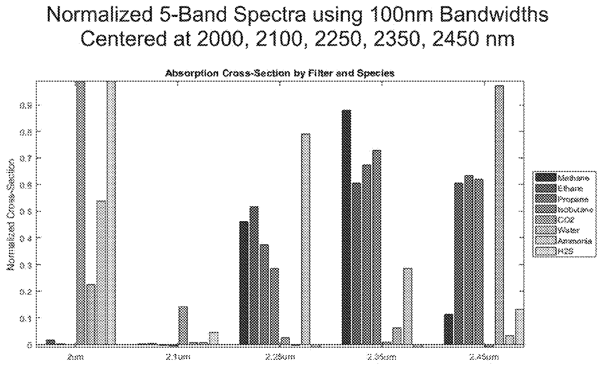
[0048]The mathematical methods that underlie this invention are described and build upon those described in U.S. Prov. Pat. Appl. No. 62 / 338,255. The description that follows may refer to methane as the gas of interest, though much of the formulation applies to other pure gases and gas mixtures except where positive buoyancy is assumed (and noted). The formulation may refer to the use of five spectral bands, however, this is only by way of example and not meant to be restrictive; this is a general multispectral formulation in the short-wave infrared. Indeed, many of the sensor designs and scanning concepts apply equally to other parts of the infrared spectrum, including mid-wave and long-wave infrared regions sometimes used for detecting gas leaks by absorption (or emission) of thermal radiation.

Principals of Gas Absorption Imaging

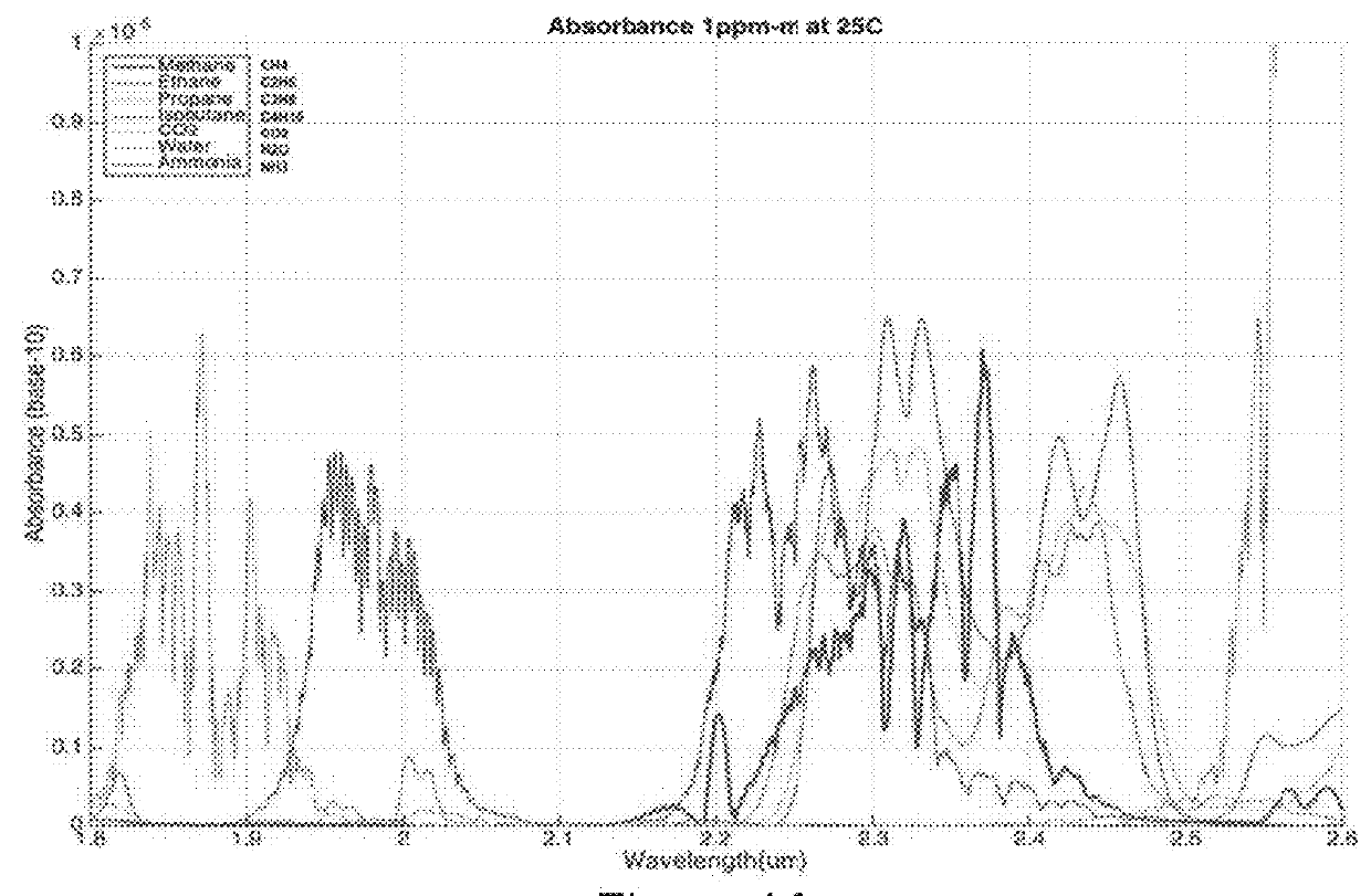
[0049]This invention detects gas leaks via differential absorption imaging spectroscopy in the range 1.9 to 2.6 microns, exploiting spectral features of h...


PUM

PropertyMeasurementUnit
wavelength rangeaaaaaaaaaa
wavelengthsaaaaaaaaaa

Abstract

Apparatus and methods for rapidly detecting, localizing, imaging, and quantifying leaks of natural gas and other hydrocarbon and greenhouse gases. Scanning sensors, scan patterns, and data processing algorithms enable monitoring a site to rapidly detect, localize, image, and quantify amounts and rates of hydrocarbon leaks. Multispectral short-wave infrared detectors sense non-thermal infrared radiation from natural solar or artificial illumination sources by differential absorption spectroscopy. A multispectral sensor is scanned to envelop an area of interest, detect the presence and location of a leak, and raster scan the area around the leak to create an image of the leak. The resulting absorption image related to differential spectral optical depth is color mapped to render the degree of gas absorption across the scene. Analysis of this optical depth image, with factors including known inline pressures and / or surface wind speed measurements, enable estimation of the leak rate, i.e., emission mass flux of gas.

Description

CROSS-REFERENCE TO RELATED APPLICATIONS[0001]This application claims priority of U.S. Provisional Patent Application No. 62 / 472,463, filed Mar. 16, 2017 and U.S. Provisional Patent Application 62 / 587,304. filed Nov. 16, 2017.STATEMENT REGARDING FEDERALLY SPONSORED RESEARCH OR DEVELOPMENT[0002](Not Applicable)SEQUENCE LISTING[0003](Not Applicable)BACKGROUND OF THE INVENTION[0004]This invention consists of sensors and algorithms to scan a site containing natural gas and related infrastructure, and automatically detect, localize, image and quantify hydrocarbon gas leaks using a short-wave infrared radiation detector in combination with multiple spectral filters under natural solar or artificial illumination. Particular embodiments recited address detection and quantification of methane gas leaks. Quantification includes total volume, total mass, and emission / leak rates of methane and other gases of interest. The invention is suitable for both gas safety (rapid detection) and emissions ...

Claims


Application Information

Patent Timeline
Patent Type & Authority Applications(United States)
IPC IPC(8): G01N21/3518G01F1/76
CPCG01N21/3518G01F1/76G01M3/38G01N2021/3513G01N21/31G01N2021/3531G01N21/3504G01J3/0297G01J3/2823G01J3/06G01J3/42G01J3/44G01J3/4412G01J5/0014
Inventor WAXMAN, ALLEN M.BYLSMA, JASON M.VAITSES, ALLAN
Owner MULTISENSOR SCI INC
Why Eureka
Try Eureka