Method for making aluminum nitride wafer and aluminum nitride wafer made by the same
a technology of aluminum nitride and aluminum nitride, which is applied in the direction of manufacturing tools, lapping machines, basic electric elements, etc., can solve the problems that the wafer is too thick and may not be able to efficiently dissipate heat, and achieves good insulating properties, high thermal conductivity, and high dielectric constant
- Summary
- Abstract
- Description
- Claims
- Application Information
AI Technical Summary
Benefits of technology
Problems solved by technology
Method used
Image
Examples
preparation example 1
um Nitride Granules
[0042]1 kg aluminum oxide and 1 kg pure aluminum powder were mixed with phenol-formaldehyde resin and carbon powder in a ball mill, before the mixture was granulated. The resulting granules were transferred into a high-temperature furnace into which acetylene, nitrogen, and hydrogen were introduced, and in which high-temperature carbothermic reduction took place at 1 atm and 1600° C. for 20 hours. The granules after the high-temperature carbothermic reduction were placed in an atmospheric environment, subjected to high-temperature decarbonization at 600° C. for 24 hours, and then granulated again with a spray granulator of OHKAWARA to produce 1.1 kg aluminum nitride granules, whose particle sizes ranged from 60 to 90 μm.
example 1
for Making an Aluminum Nitride Wafer
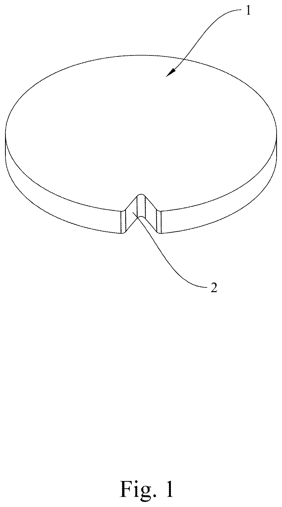
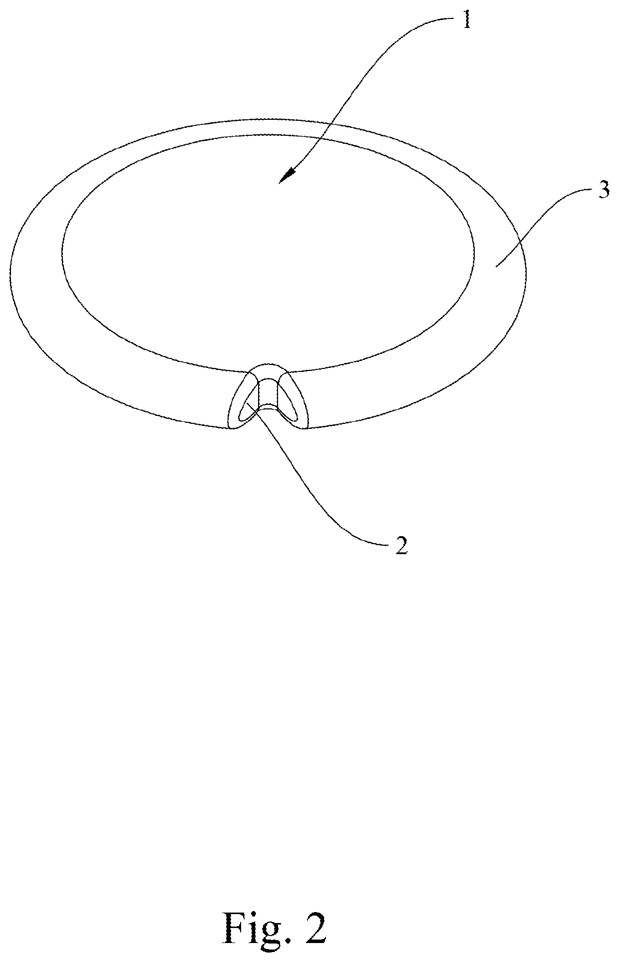
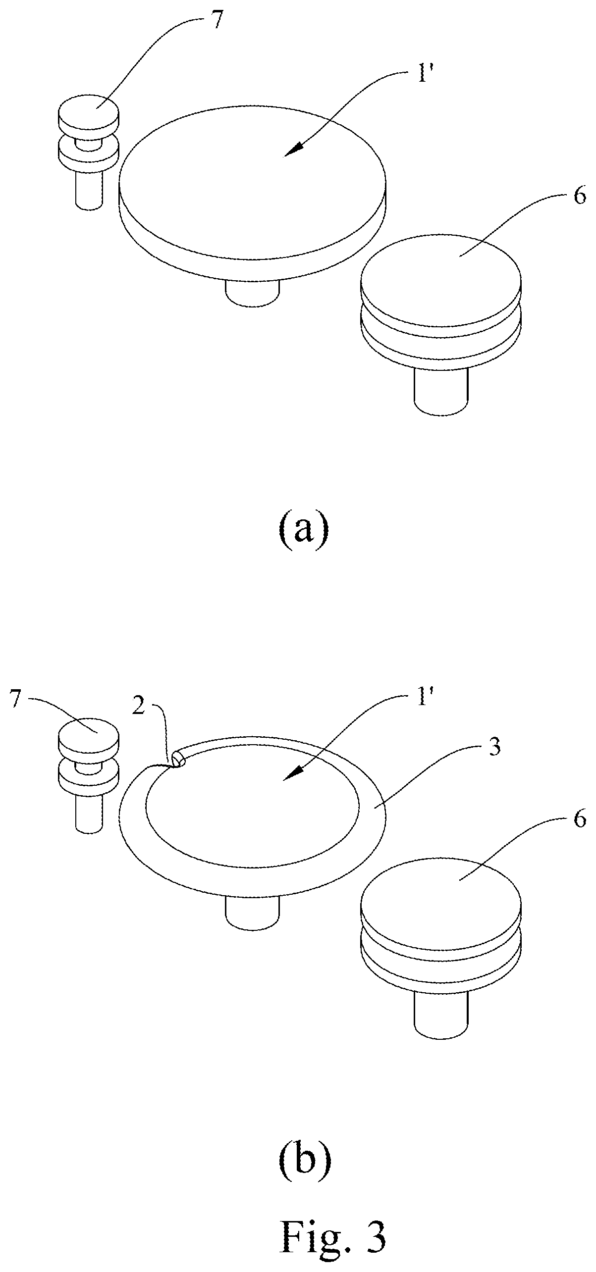
[0043]3 kg aluminum nitride granules from preparation example 1 were added and mixed with 10% PVB resin and 1% dispersant to produce an aluminum nitride green body. The aluminum nitride green body was put into a mold in an oil hydraulic press and shaped in vacuum (the pressure in the mold being −0.063 atm) under a molding force of 1961330 N, before isostatic pressing was carried out by a water hydraulic press at 30° C. and 3000 atm to produce an aluminum nitride green-body block. The aluminum nitride green-body block was debinding at 600° C. in an atmospheric environment and subsequently sintered at 10 atm and 1800° C. in a high-temperature furnace of SHIMADZU to form an aluminum nitride wafer block. The aluminum nitride wafer block was transferred to a wheel grinder so as to form an alignment notch in the aluminum nitride wafer block, and after that, the aluminum nitride wafer block was cut with a multi-line cutting machine into 8-inch aluminum n...
example 2
for Making an Aluminum Nitride Wafer
[0044]3 kg aluminum nitride granules from preparation example 1 were added and mixed with 10% PVB resin and 1% dispersant to produce an aluminum nitride green body. An aluminum nitride green-body slice was then formed by a tape-casting process and was dried at 60° C. for 10 minutes. The dried aluminum nitride green-body slice was debinding at 600° C. in an atmospheric environment and then sintered at 1 atm and 1800° C. in a high-temperature furnace of SHIMADZU to form an aluminum nitride wafer slice, which was subsequently moved to a laser cutting machine in order to form an alignment notch in the periphery of the aluminum nitride wafer slice and cut the aluminum nitride wafer slice into an 8-inch circle. The resulting aluminum nitride wafer slice was wet-lapped on both sides by a bi-directional grinder and then thinned down to the desired thickness by a unidirectional thinning machine. Also, the periphery of the aluminum nitride wafer slice was c...
PUM
| Property | Measurement | Unit |
|---|---|---|
| temperature | aaaaa | aaaaa |
| pressure | aaaaa | aaaaa |
| pressure | aaaaa | aaaaa |
Abstract
Description
Claims
Application Information
 - R&D
- Intellectual Property
- Life Sciences
- Materials
- Tech Scout
- Unparalleled Data Quality
- Higher Quality Content
- 60% Fewer Hallucinations
Browse by: Latest US Patents, China's latest patents, Technical Efficacy Thesaurus, Application Domain, Technology Topic, Popular Technical Reports.
© 2025 PatSnap. All rights reserved.Legal|Privacy policy|Modern Slavery Act Transparency Statement|Sitemap|About US| Contact US: help@patsnap.com


