Microfluidic cell culture devices

Pending Publication Date: 2022-04-07
MASSACHUSETTS INST OF TECH
View PDF0 Cites 0 Cited by
  • Summary
  • Abstract
  • Description
  • Claims
  • Application Information

AI Technical Summary

Benefits of technology

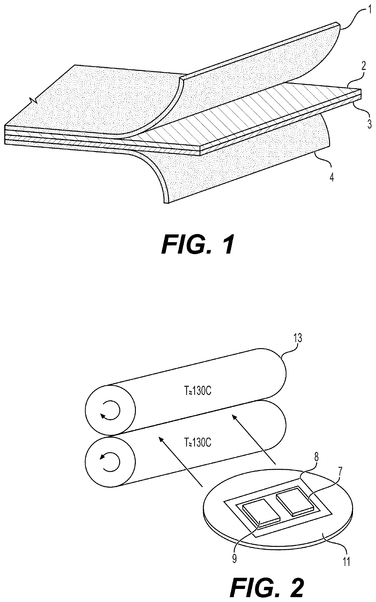
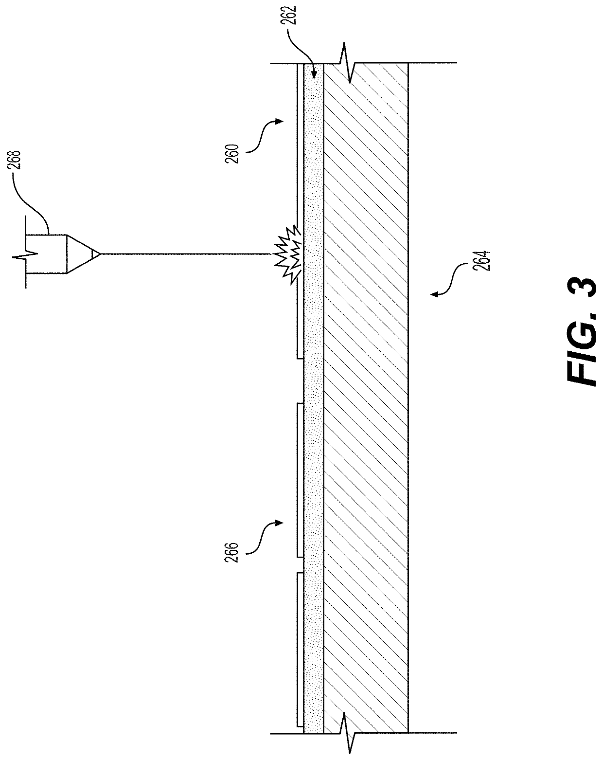
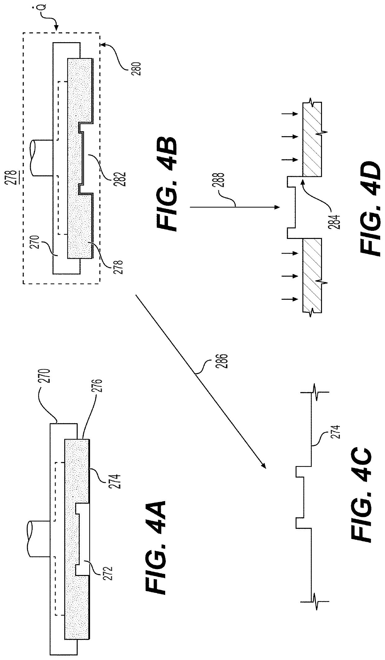
The patent describes a special film that allows for easy fabrication of microfluidic chips with optical windows. It can be easily attached to a substrate using a heat press or laser and can be made using a roll lamination process or conventional laser fabrication techniques. Additionally, the patent explains how scaffolds made from various extracellular matrix materials can be laser cut and used in microfluidic chips and transwell inserts. These scaffolds can be imageable using optically clear thin films and can incorporate hydrophobic materials. The technical effects include simplified and efficient fabrication of microfluidic chips with optical windows and the ability to incorporate extracellular matrix materials.

Problems solved by technology

While these platforms are useful for growing and proliferating cells to be used in subsequent experiments, they are not ideal environments to monitor cell responses to stimuli as cells cannot freely move or perform functions as observed in vivo that are dependent on cell-extracellular matrix material interactions.
However, lack of clinical efficacy, rather than toxicity, was identified as the leading cause of drug attrition in Phase II and III clinical trials (the most costly stage) (Kubinyi H, Nat Rev Drug Discov 2(8):665-668 (2003); Cook D, et al.
While toxicology and pharmacodynamic studies are common applications, pharmacokinetic studies have been limited in multi-MPS platforms.
Fabrication material is crucial in the design of a cell culture device as not all polymers are biocompatible, with some materials such as PDMS causing undesirable adsorption or absorption of small molecules.
Additionally, uncured PDMS oligomers can leach into the cell culture media, which can harm the microenvironment.
The ability to fabricate devices using these materials poses some unique challenges which has inhibited their ubiquity in the microfluidics community.
PDMS devices are usually molded and plasma bonded to a glass microscope slide, a process that is not feasible for thermoplastic polymers.
Lamination of optically clear thermoplastic microfluidic devices often requires expensive equipment (e.g., ultrasonic welding, laser welding) and is prone to low strength and unreliable bonds between the device and the optical window.

Method used


Image

  • Microfluidic cell culture devices
  • Microfluidic cell culture devices
  • Microfluidic cell culture devices

Examples


Embodiment Construction

I. Definitions

[0069]The term “microfluidic” refers to a system that involves the control and manipulation of small fluid volumes in channels with dimensions on the order of a few micrometers up to a few millimeters and total system volumes on the scale of nanoliters to a few milliliters. As used herein, the term “channel” refers to a closed volume where fluid passage occurs. A channel may vary in cross sectional area and length. A channel may have square, circular or other cross-sectional shape.

[0070]The term “chip” refers to the component where microfluidic fluid manipulation occurs. A chip may be made of a wide variety of materials and can be different sizes. A “device” refers to a chip or microfluidic system that performs a function or series of functions. A device may consist of one or more chips.

[0071]As used herein, the term “hydrogel” refers to a substance formed when an organic polymer (natural or synthetic) is cross-linked via covalent, ionic, or hydrogen bonds to create a ...


PUM

PropertyMeasurementUnit
Fractionaaaaaaaaaa
Fractionaaaaaaaaaa
Displacementaaaaaaaaaa

Abstract

Materials and methods of making have been developed for mass production of thermoplastic microfluidic chips. An elastomer diaphragm with a stress relieving feature can be used in microfluidic valves, pump diaphragms, and diaphragm micropumps. An optimized pump chamber design for complete fluid displacement and chamber geometry are provided. Microfluidic pressure regulators use a pneumatically actuated elastic membrane in a back-pressure regulator configuration. Microfluidic accumulators store pressurized fluid in a microfluidic chip. Removable caps for cell culture and a quick release top are described. Methods to incorporate hydrogels and ECM scaffolds have been developed. Electro pneumatic manifolds connect and control of multiple microfluidic devices vertically or on a rotary mechanism.

Description

CROSS REFERENCE TO RELATED APPLICATIONS[0001]This application claims the benefit of and priority to U.S. Provisional Application No. 63 / 088,900 filed Oct. 7, 2020, which is hereby incorporated herein by reference in its entirety.FIELD OF THE INVENTION[0002]The present invention is generally in the field of manufacturing processes and components used in microfluidic cell culture devices.BACKGROUND OF THE INVENTION[0003]Microfluidics refers to the behavior, precise control, and manipulation of fluids that are geometrically constrained to a small scale (typically sub-millimeter). It is a multidisciplinary field that involves engineering, physics, chemistry, biochemistry, nanotechnology, and biotechnology. Microfluidics has practical applications in the design of systems that process low volumes of fluids to achieve multiplexing, automation, and high-throughput screening.[0004]Microfluidic cell culture integrates knowledge from biology, biochemistry, engineering, and physics to develop ...

Claims


Application Information

Patent Timeline
IPC IPC(8): B01L3/00
CPCB01L3/502707B01L2200/0689B01L2200/12B01L2200/16B01L2300/0887B01L2300/0819B01L2300/123B01L2400/049B01L2300/069C12M23/16C12M41/40C12M29/00B01L3/50273B01L3/502738B29C65/16B01L2300/0816B01L2400/0655B01L2400/0481B01L2400/0487B01L2200/027B01L3/502715B01L9/527B01L9/50B01L2300/042F16K99/0015F16K99/0059B29C65/08B29L2031/756B29C65/18B29C66/83413B29C66/1122B29C66/472B29C66/919B29C66/71H01L21/4885B81B2201/036B81B2201/054B81C2201/0143B81C2201/034B81B2203/0127B81C1/00158B81C2203/036B29K2023/38B29K2067/003
Inventor O'BOYLE, DUNCAN A.GRIFFITH, LINDATRUMPER, DAVID
Owner MASSACHUSETTS INST OF TECH
Why Eureka
Try Eureka