
Reflective diffraction grating resistant to an ultra-short-pulse light flux with high peak power and method for the production thereof

Pending Publication Date: 2022-06-09
HORIBA FRANCE SAS
View PDF0 Cites 0 Cited by
  • Summary
  • Abstract
  • Description
  • Claims
  • Application Information

AI Technical Summary

Benefits of technology

The invention is a diffraction grating that includes an intermediate metal layer between the external reflective layer and the substrate surface. The external reflective layer is composed of a first metal, while the intermediate metal layer is composed of a second metal with higher electron-phonon coupling. The external reflective layer has a specific thickness range to increase high peak power ultrashort pulse light flux resistance. The reflective diffraction grating can be fabricated according to the above steps. The technical effect of the invention is to improve the performance of diffraction gratings in resisting high peak power ultrashort pulse light.

Problems solved by technology

Now, the maximum achievable power is limited by the flux resistance of the laser chain optical components.
However, the risk of destroying an optical component persists in the stage that performs the pulse compression, based in particular on the use of diffraction gratings.
For pulse compression in the infrared domain (at 800 nm, 1053 nm or 1550 nm), aluminum gratings are not used because their diffraction efficiency, generally less than 90%, is not sufficient.
On the other hand, silver diffraction gratings are oxidizable and thus not much used.
However, gold-based gratings suffer from a limited laser flux resistance in the femtosecond regime.
However, MLD gratings are more complicated and thus more expensive to fabricate than metal gratings.
In addition, MLD gratings have a too limited spectral bandwidth (a few tens of nm) to be used on the ultrashort pulse (<50 fs) laser chains.
An MLD diffraction grating cannot have this type of bandwidth performance.
However, the modelling of the physical phenomena in ultrashort light pulse regime is very difficult and does not make it possible, in the current state of knowledge, to predict the response of any diffraction grating to an intense laser flux and even less to propose a diffraction grating structure having at the same time an improved flux resistance and a high diffraction efficiency on a wide spectral bandwidth.

Method used


Image

  • Reflective diffraction grating resistant to an ultra-short-pulse light flux with high peak power and method for the production thereof

Examples


Embodiment Construction

[0044]The present disclosure relates in particular to a method for improving the laser flux resistance of metal reflective diffraction gratings subjected to ultra-intense and ultrashort laser pulses (pulse duration <500 fs).

[0045]The current working spectral domain in the field of ultrashort lasers is located in the near infrared (700 nm-1100 nm). The ultrashort pulses are mainly made at a central wavelength of 800 nm, the middle of the gain range of the Ti:sapphire crystal the most commonly used in the ultrashort pulse laser chains.

[0046]The fabrication of a diffraction grating will now be considered.

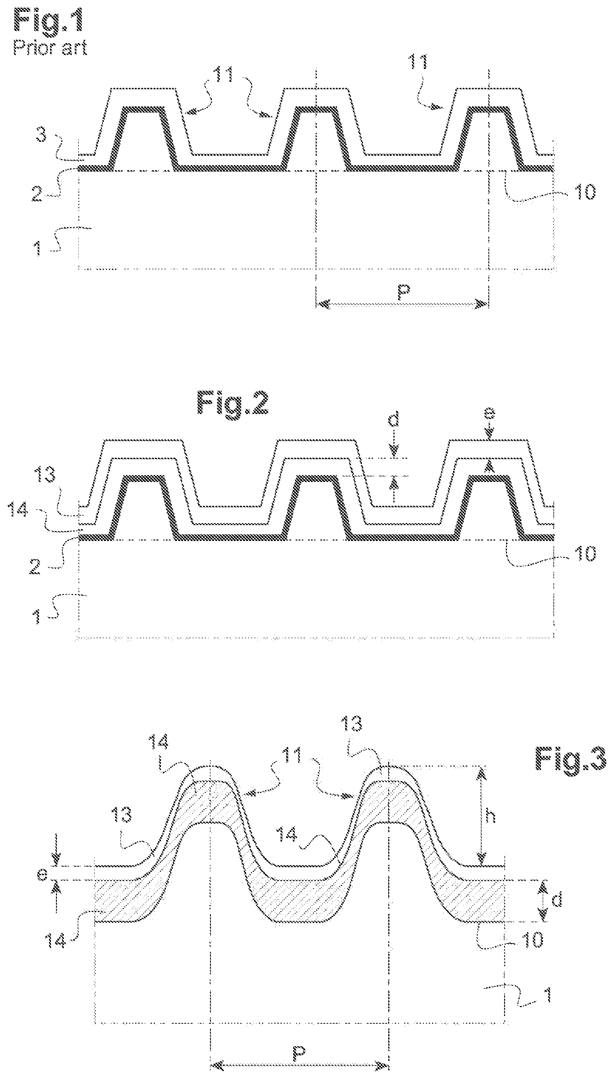
[0047]The substrate 1 is generally made of silica, silicon or formed from an optical ceramic matrix (for example, of the Zerodur, Pyrex or BK7 type). A surface 10 of the substrate 1 is previously polished in such a way as to have a residual surface roughness less than a fraction of the wavelength used. The surface 10 can be planar, concave or convex. By a method known by the one skille...


PUM


Abstract

Disclosed is a reflective diffraction grating including at least one intermediate metal layer arranged between the external reflective layer and a surface of the substrate including the grating lines, the external reflective layer being consisted of a first metal and the intermediate metal layer being consisted of another metal, the other metal having a higher electron-phonon coupling coefficient than the electron-phonon coupling coefficient of the first metal or metal alloy, the external reflective layer having a thickness in a range having a lower limit determined by a reflection coefficient of the first metal and an upper limit determined by a thermal diffusion length of the first metal, and the intermediate metal layer having another thickness greater than a minimum value in such a way as to increase the high peak power ultrashort pulse light flux resistance of the reflective diffraction grating.

Description

TECHNICAL FIELD[0001]The present invention generally relates to the field of diffraction gratings used in high power lasers, for example for laser pulse compression.[0002]More particularly, it relates to a high peak power ultrashort pulse laser flux-resistant reflective diffraction grating. It also relates to the method for fabricating such a grating.PRIOR ART[0003]Research, in particular in the field of nuclear fusion, plasma physics and fundamental physics, nowadays uses ultrashort pulse lasers (whose pulse duration is less than ˜500 fs) with higher and higher energies in order to reach peak powers approaching or exceeding a petawatt (PW).[0004]Now, the maximum achievable power is limited by the flux resistance of the laser chain optical components. The laser flux resistance of an optical component depends in particular on the pulse energy density per surface unit and duration.[0005]The damage threshold problems of optical components in high energy pulse lasers have been partially...

Claims


Application Information

Patent Timeline
IPC IPC(8): G02B5/18
CPCG02B5/1861Y02E30/10
Inventor FEILLEUX, ROMAINBOUSSADI, AMINE
Owner HORIBA FRANCE SAS
Learn More