Catalytic multi-stage process for hydroconversion and refining hydrocarbon feeds

a hydroconversion and hydrocarbon feed technology, applied in the direction of catalyst activation/preparation, metal/metal-oxide/metal-hydroxide catalyst, physical/chemical process catalyst, etc., can solve the problem of low effectiveness of known iron-based catalytic compounds, poor contact with feed materials, and particulate support catalysts. problem, to achieve the effect of enhancing distillate yield and quality and high quality

Inactive Publication Date: 2001-02-20
HEADWATERS CTL
View PDF1 Cites 267 Cited by
  • Summary
  • Abstract
  • Description
  • Claims
  • Application Information

AI Technical Summary

Benefits of technology

The present invention advantageously provides an improved catalytic multi-stage process for hydroprocessing heavy hydrocarbon feed materials to produce low-boiling hydrocarbon liquid products, by utilizing two-staged dispersed catalyst reactors with successive primary and secondary interstage phase separators and a catalytic fixed bed in-line hydrotreater for enhancing distillate yield and quality, and by improving the second stage reactor kinetics to hydrotreat C.sub.4 -750.degree. F. distillates and enable removal of oxygen contained in the feed as a carbon oxide instead of consuming hydrogen in the undesirable formation of water. Prior catalytic hydrogenation processes for such carbonaceous feed materials do not incorporate the unique balance provided by the present process, i.e., the combination of utilizing highly dispersed iron-based slurried catalysts in the reactors, the interstage phase separations for removal of light hydrocarbon vapors the in-line pressurized catalytic fixed bed hydrotreating step so that only a higher boiling bottoms liquid fraction is passed on to th

Problems solved by technology

However, because of the generally low effectiveness of such known iron-based catalytic compounds, primarily due to their low initial surface areas and inability to provide high levels of dispersion under reaction conditions, catalytic hydroconversion processes for coal and heavy petroleum resid feedstocks which have been developed during the past 30 years have usually utilized a bed of particulate supported type catalysts in the reactors.
Although such particulate supported type catalysts such as cobalt-molybdenum or nickel-molybdenum deposited on alumina or silica supports and catalytic hydroconversion processes using the supported catalysts have provided generally good results for hydrogenation and hydroconversion of coal and heavy oil feed materials, some disadvantages of such particulate supported type catalysts are their relatively poor contact with the feed materials and their rapid deactivation caused by deposition on the catalyst of coke and metal contaminants such as iron, nickel, titanium and vanadium contained in the feeds.
U.S. Pat. No. 4,136,013 to Moll et al discloses an emulsion type metal catalyst useful for hydrogenation processes, but it also has disadvantages of lo

Method used


Image

  • Catalytic multi-stage process for hydroconversion and refining hydrocarbon feeds
  • Catalytic multi-stage process for hydroconversion and refining hydrocarbon feeds
  • Catalytic multi-stage process for hydroconversion and refining hydrocarbon feeds

Examples


example 2

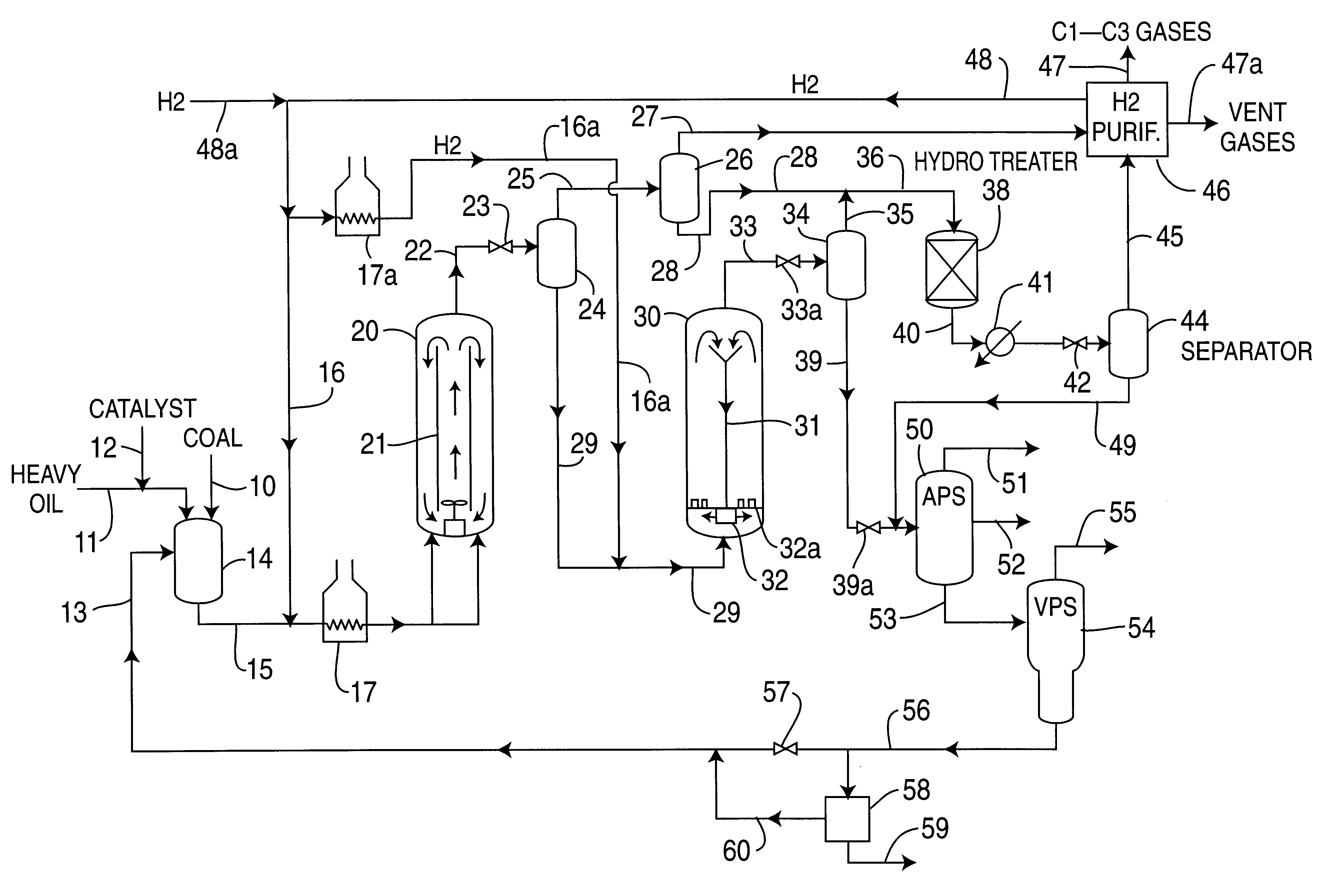
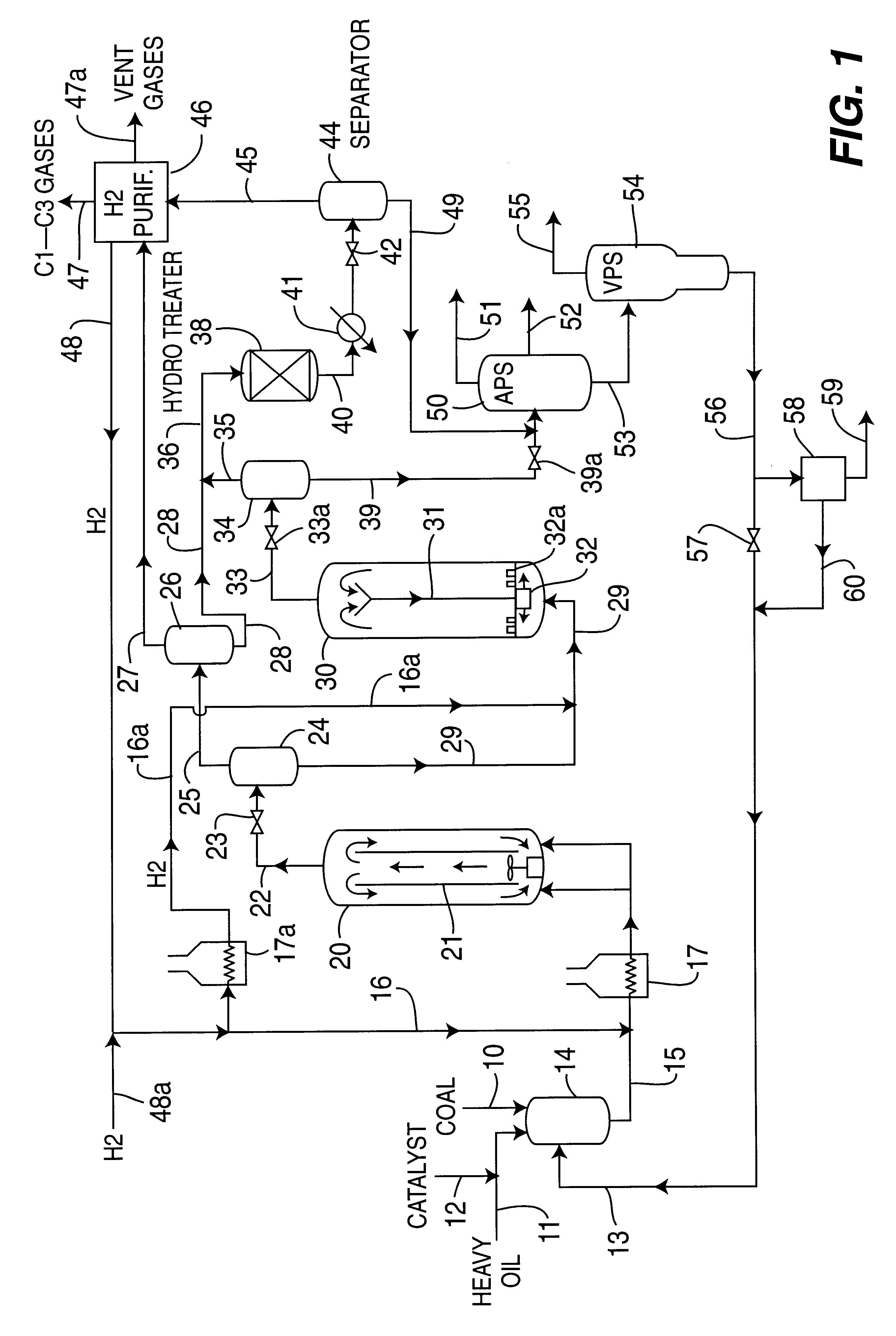
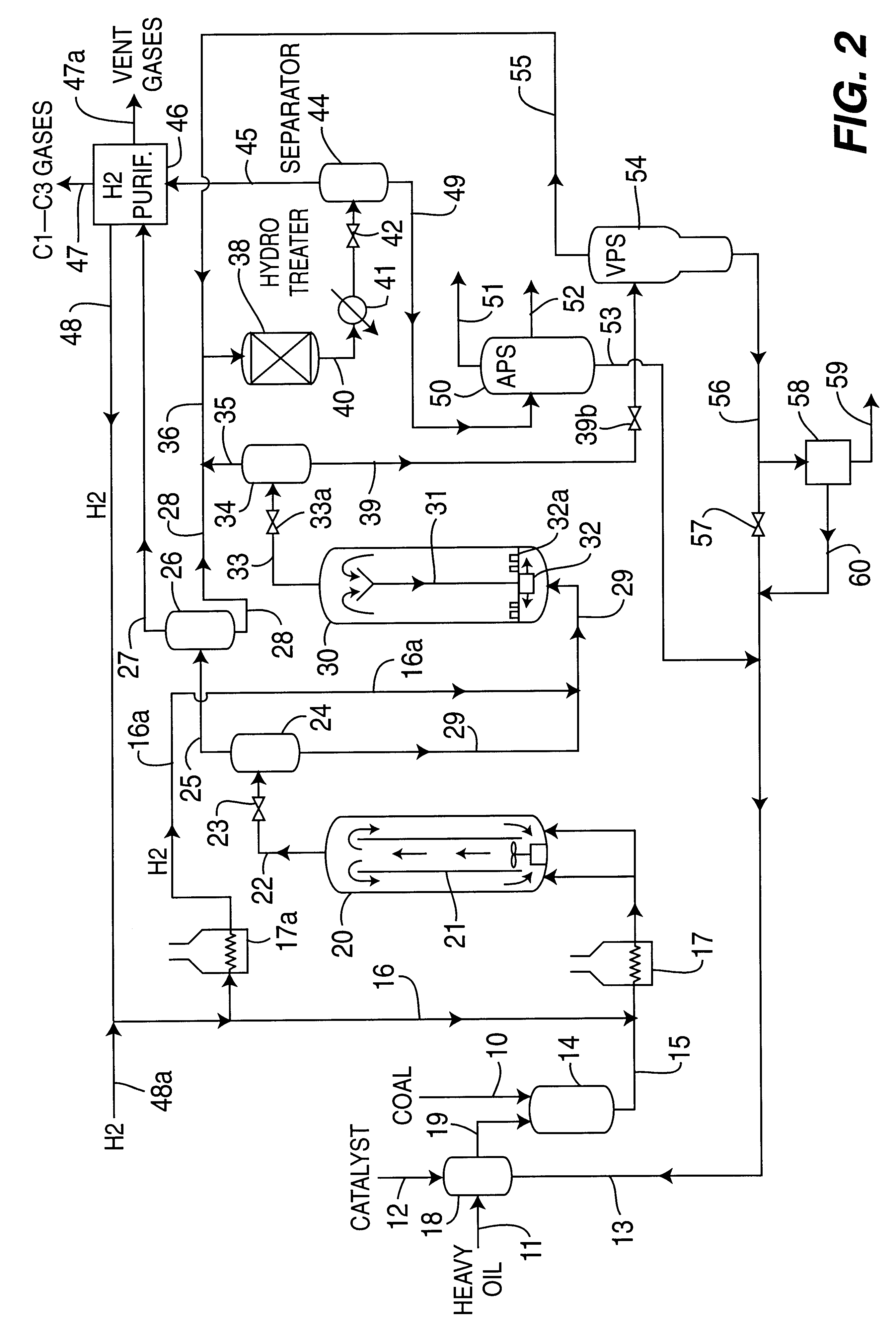
A further comparison was made for a catalytic two-stage reactor hydrogenation process with and without interstage phase separation for a blended feedstream of 35 wt. %sub-bituminous coal and 65% Hondo petroleum resid. The results are provided in Table 3 below.

TABLE 3 Without With Interstage Interstage Separation Separation Normalized Yields, w % MAF Feed Relative Reaction Severity 43 46 C.sub.1 -C.sub.3 Gases 6.2 7.3 C.sub.4 -C.sub.7 Liquid 9.7 9.3 Naphtha (C.sub.4 -3250.degree. F.) 17.7 21.6 Mid-Distillate (350-650.degree. F.) 31.5 37.3 Heavy Distillate (650-975.degree. F.) 26.7 20.1 Resid (975.degree. F..sup.+) 10.4 7.5 Process Performance, wt. % MAF Feed Coal Conversion 92.6 95.7 975.degree. F. Resid Conversion 85.4 89.8 C.sub.4 -975.degree. F. Product Yield 75.8 79.1 H.sub.2 Consumption 4.45 4.78

From these results, it is seen that generally higher conversion of the blended coal and resid feed and higher C.sub.4 -975.degree. F. product yield are achieved at similar reaction condi...

example 3

Utilizing an in-line catalytic hydrotreating step for the combined two staged reactor effluent vapor and light liquid fraction streams in this catalytic two-stage hydrogenation process is a very effective and economical step for reducing heteroatom content and aromatics in the product oil. The exothenm available from hydrogenation of the coal or heavy hydrocarbon oil feed and the high hydrogen partial pressure which is available from the prior reactors is utilized effectively in the catalytic in-line hydrotreating reactor, and a significant $3-$6 / bbl improvement in product oil value is realized. Typical comparative results for in-line catalytic hydrotreating of a naphtha fraction derived from two-stage catalytic reactor operations on a sub-bituminous coal feed are shown in Table 4 below:

TABLE 4 Quality Of In-line Hydrotreated Naphtha Fraction Product Characteristics In-line Hydrotreating No Yes .degree.API Gravity 36.2 39.9 Carbon, wt. % 86.6 86.3 Hydrogen, wt. % 13.3 13.7 Nitrogen,...

example 4

A direct comparison of a known prior catalytic two-stage liquefaction (CTSL) process using two staged close-coupled ebullated bed reactors each containing a particulate supported type catalyst or a dispersed type catalyst compared with the present catalytic two-stage reaction process utilizing highly dispersed iron-based slurry catalyst together with interstage phase separation and in-line catalytic hydrotreating step for a sub-bituminous coal feed is shown below in Table 6.

TABLE 6 Catalytic Two Stage Coal Liquefaction of Sub-Bituminous Coal Feed Supported Dispersed Particulate Catalyst GelCat .TM. Process Arrangement Catalyst Iron / Moly Iron / Moly / P Run Designation CC-1 CMSL-6 PB-04 Interstage Phase Separation None None Yes In-Line Catalytic Hydrotreating None None Yes Performance, wt. % MAF Coal C.sub.1 -C.sub.3 Gases 8.0 8.0 7.9 CO.sub.x 0.5 4.5 6.5 H.sub.2 O 18.5 14.0 12.1 Coal Conversion 86.4 94.1 93.2 C.sub.4 -975.degree. F. Liquid Fraction 62.6 63.1 67.5 975.degree. F..sup.+ Fr...


PUM

PropertyMeasurementUnit
Timeaaaaaaaaaa
Partial pressureaaaaaaaaaa

Abstract

A multi-stage catalytic hydrogenation and hydroconversion process for heavy hydrocarbon feed materials such as coal, heavy petroleum fractions, and plastic waste materials. In the process, the feedstock is reacted in a first-stage, back-mixed catalytic reactor with a highly dispersed iron-based catalyst having a powder, gel or liquid form. The reactor effluent is pressure-reduced, vapors and light distillate fractions are removed overhead, and the heavier liquid fraction is fed to a second stage back-mixed catalytic reactor. The first and second stage catalytic reactors are operated at 700-850.degree. F. temperature, 1000-3500 psig hydrogen partial pressure and 20-80 lb./hr per ft.sup.3 reactor space velocity. The vapor and light distillates liquid fractions removed from both the first and second stage reactor effluent streams are combined and passed to an in-line, fixed-bed catalytic hydrotreater for heteroatom removal and for producing high quality naphtha and mid-distillate or a full-range distillate product. The remaining separator bottoms liquid fractions are distilled at successive atmospheric and vacuum pressures, low and intermediate-boiling hydrocarbon liquid products are withdrawn, and heavier distillate fractions are recycled and further upgraded to provide additional low-boiling hydrocarbon liquid products. This catalytic multistage hydrogenation process provides improved flexibility for hydroprocessing the various carbonaceous feedstocks and adjusting to desired product structures and for improved economy of operations.

Description

BACKGROUND OF INVENTIONThis invention pertains to a catalytic multistage process for hydrogenation and hydroconversion of heavy hydrocarbon feed materials by utilizing a highly-dispersed iron-based catalyst to produce lower-boiling hydrocarbon liquid fuel products. The invention pertains particularly to such catalytic multi-stage hydrogenation process utilizing an in-line catalytic hydrotreating step for feedstreams of coal, heavy petroleum residua, plastic wastes, and combinations thereof.Coal hydrogenation and liquefaction processes using various iron-containing compounds such as pyrites (FeS.sub.2) and red mud (Fe.sub.2 O.sub.3) as catalysts have been well known for many years. Such particulate iron-containing catalyst compounds were usually added in small amounts to a coal-oil slurry feedstream upstream of a catalytic reactor operated at elevated temperature and pressure conditions. However, because of the generally low effectiveness of such known iron-based catalytic compounds,...

Claims


Application Information

Patent Timeline
IPC IPC(8): B01J27/14B01J27/185B01J23/76B01J23/745B01J27/053B01J23/881B01J35/00B01J35/12B01J37/00B01J37/03C10G47/02C10G65/10C10G65/02C10G47/00C10G65/00C10G1/08C10G1/00B01J27/19B01J23/84B01J23/74C10G1/10C10G47/26C10G49/12
CPCB01J23/745B01J23/881B01J27/053B01J27/1853B01J35/12B01J37/036C10G1/002C10G1/006C10G1/086C10G1/10C10G47/02C10G47/26C10G49/12C10G65/02C10G65/10B01J23/74B01J23/84B01J27/19
Inventor COMOLLI, ALFRED G.LEE, LAP-KEUNG
Owner HEADWATERS CTL
Why Eureka
Try Eureka