Method of and apparatus for controlling fluid flow and electric fields involved in the electroplating of substantially flat workpieces and the like and more generally controlling fluid flow in the processing of other work piece surfaces as well

a technology of fluid flow and electric field, which is applied in the direction of electric circuits, manufacturing tools, coatings, etc., can solve the problems of uneven fluid distribution in the electroplating chamber, difficult to design equipment capable of producing substantially uniform metal films, and thicker plated deposits near the outer edge of the workpiece, etc., to achieve tighter packing of process chambers, increase the workpiece throughput per cluster tool, and improve the effect of capital utilization

Inactive Publication Date: 2001-06-26
HERCULES TECH GROWTH CAPITAL +1
View PDF6 Cites 129 Cited by
  • Summary
  • Abstract
  • Description
  • Claims
  • Application Information

AI Technical Summary

Benefits of technology

A rotational reciprocating agitator is disposed between each cathode workpiece and its anode within each cylindrical electroplating chamber of the stack, or may be located between the bottom and top planes of other wet processes such as etching or cleaning chambers. In the preferred electroplating application, however, the agitator is composed of a plurality of radially extending blades that are shaped and configured such that rotation of the agitator about a central chamber longitudinal axis perpendicular to the parallel cathode and anode planes and aligned with the center of the cathode, causes fluid within the chamber to be evenly and repeatedly mixed throughout the chamber, especially laterally at the workpiece cathode surface. In addition, the blades have a cross-sectional shape parallel to the plane of the cathode and anode that preferably is substantially a radial wedge or sector of constant angle. Consequently, the radial uniformity of the time-averaged electric field between the cathode and anode is not disrupted by the movement of the agitator itself as it reciprocatingly rotates around the longitudinal axis. The use of reciprocating rotational motion in the present invention to mix the plating solution in the chamber, as distinguished from continuous rotational fluid motion that, as earlier stated, causes fluid particles to travel in circles known as Coriolis motion, breaks up this pattern and causes thorough and uniform mixing throughout all parts of the chamber and along the workpiece surface. Experimentation shows that such fluid agitation is strong enough to break up entrapped gas bubbles and carry them out of the chamber along with the fluid overflow. Even with the worst-case condition created by injecting air into the chamber, the air is prohibited by the reciprocating agitator motion from attaching to the workpiece surface, avoiding deleterious non-uniform electroplating deposition on said surface.
The design of the chamber, furthermore, produces this thorough solution mixing at the workpiece surface with a very desirable short axial chamber length. This compact vertical size allows for t

Problems solved by technology

At least three factors, however, make it difficult to design equipment that is capable of producing substantially uniform metal films.
First, the plating current spreads out when passing from the anode to the cathode, usually resulting in thicker plated deposits near the outer edge of the workpiece.
Secondly, the fluid distribution in the electroplating chamber, particularly at the anode and cathode surfaces, may not be uniform.
Non-uniform fluid distribution at the cathode, for example, can cause variation of the diffusion boundary layer thickness across the workpiece surface, which, in turn, can lead to non-uniform plated metal thickness and non-uniform alloy composition.
Thirdly, the ohmic potential drop from the point on the workpiece at which the electroplating current enters the workpiece may be non-uniform across the workpiece surface, leading to variation in plating current at the workpiece surface and consequently leading to non-uniform metal film deposition.
Unfortunately, however, this arrangement is difficult to incorporate in a machine that automatically loads and unloads workpieces in and from the plating chamber.
This approach, however, requires workpiece attachment means which are difficult to automate for manufacturing.
While in a cluster tool, the compactness of the plating chamber is important for maximizing the economy of the manufacturing process, such prior art fountain plating chambers are decidedly not economical in this regard.
Because they require an amount of fluid flow proportional to the cathode area, however, these techniques are not practical for substantially large workpieces such as, for example, 200 millimeter and 300 millimeter silicon wafers for which the present invention, with its adequate fluid agitation near th

Method used


Image

  • Method of and apparatus for controlling fluid flow and electric fields involved in the electroplating of substantially flat workpieces and the like and more generally controlling fluid flow in the processing of other work piece surfaces as well
  • Method of and apparatus for controlling fluid flow and electric fields involved in the electroplating of substantially flat workpieces and the like and more generally controlling fluid flow in the processing of other work piece surfaces as well
  • Method of and apparatus for controlling fluid flow and electric fields involved in the electroplating of substantially flat workpieces and the like and more generally controlling fluid flow in the processing of other work piece surfaces as well

Examples


Embodiment Construction

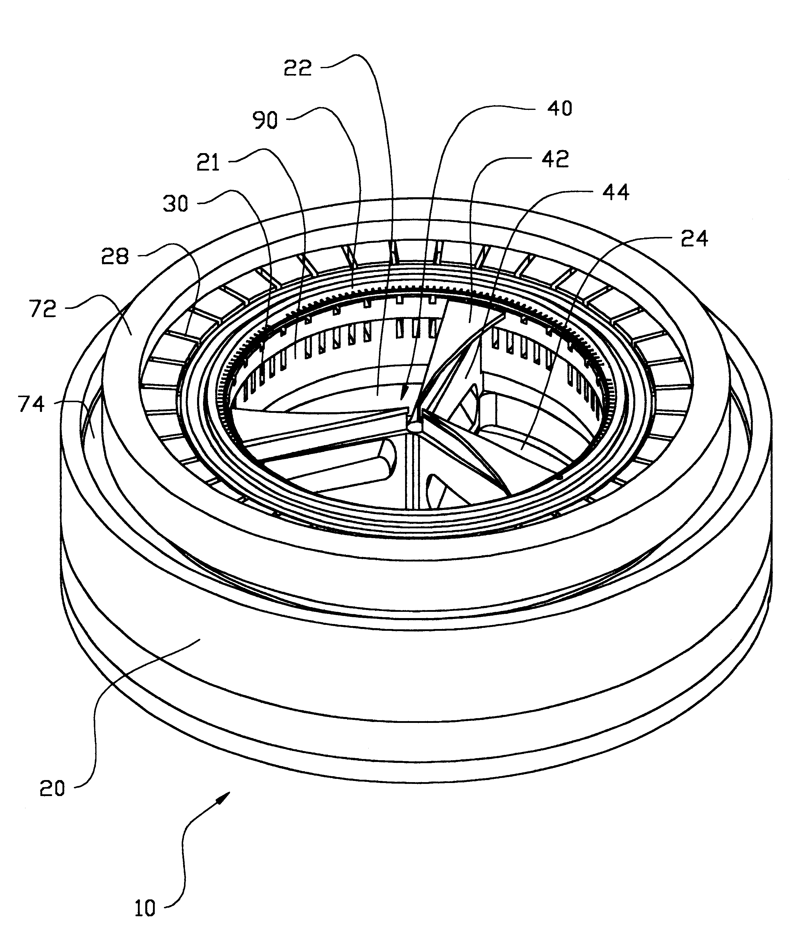
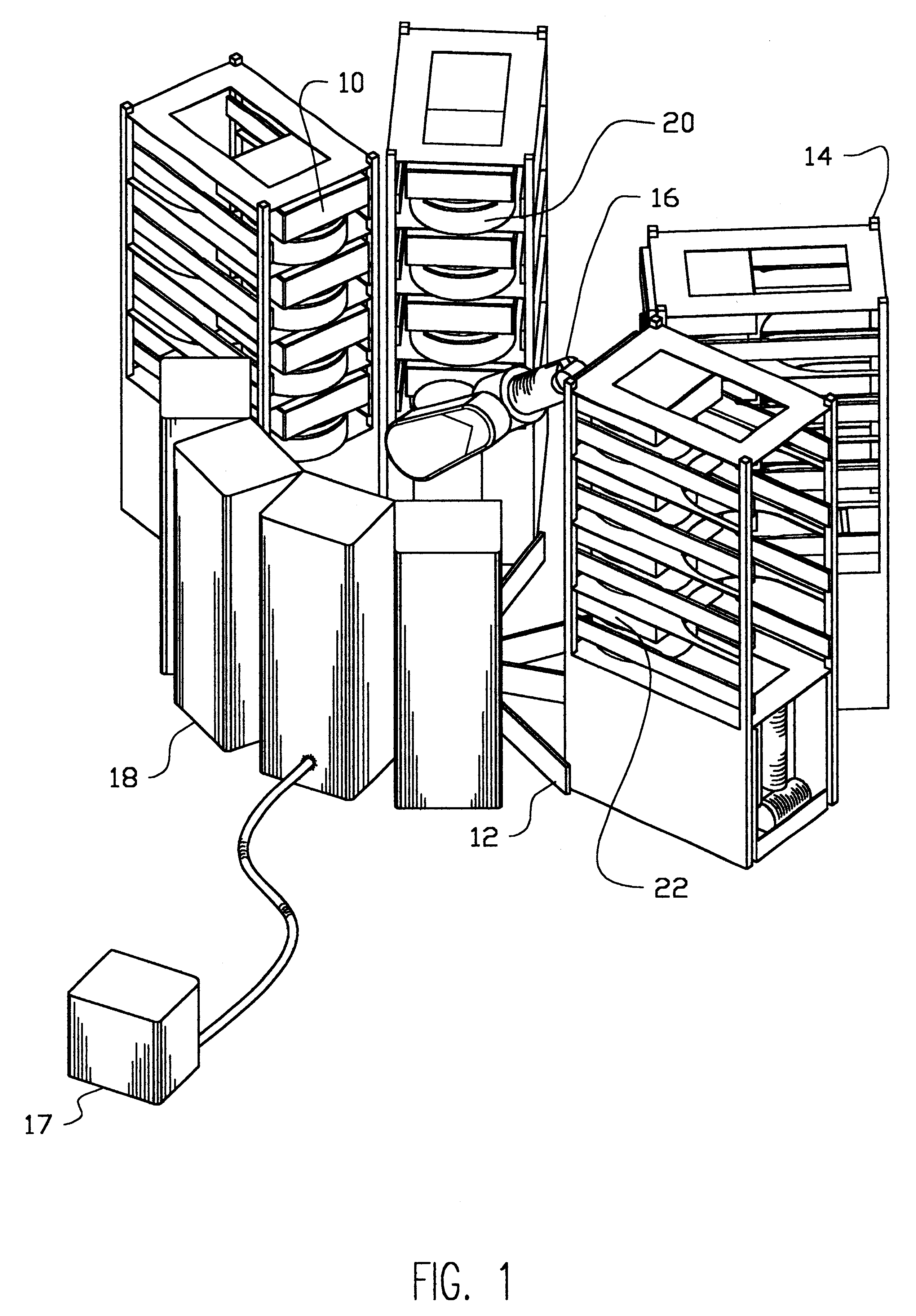
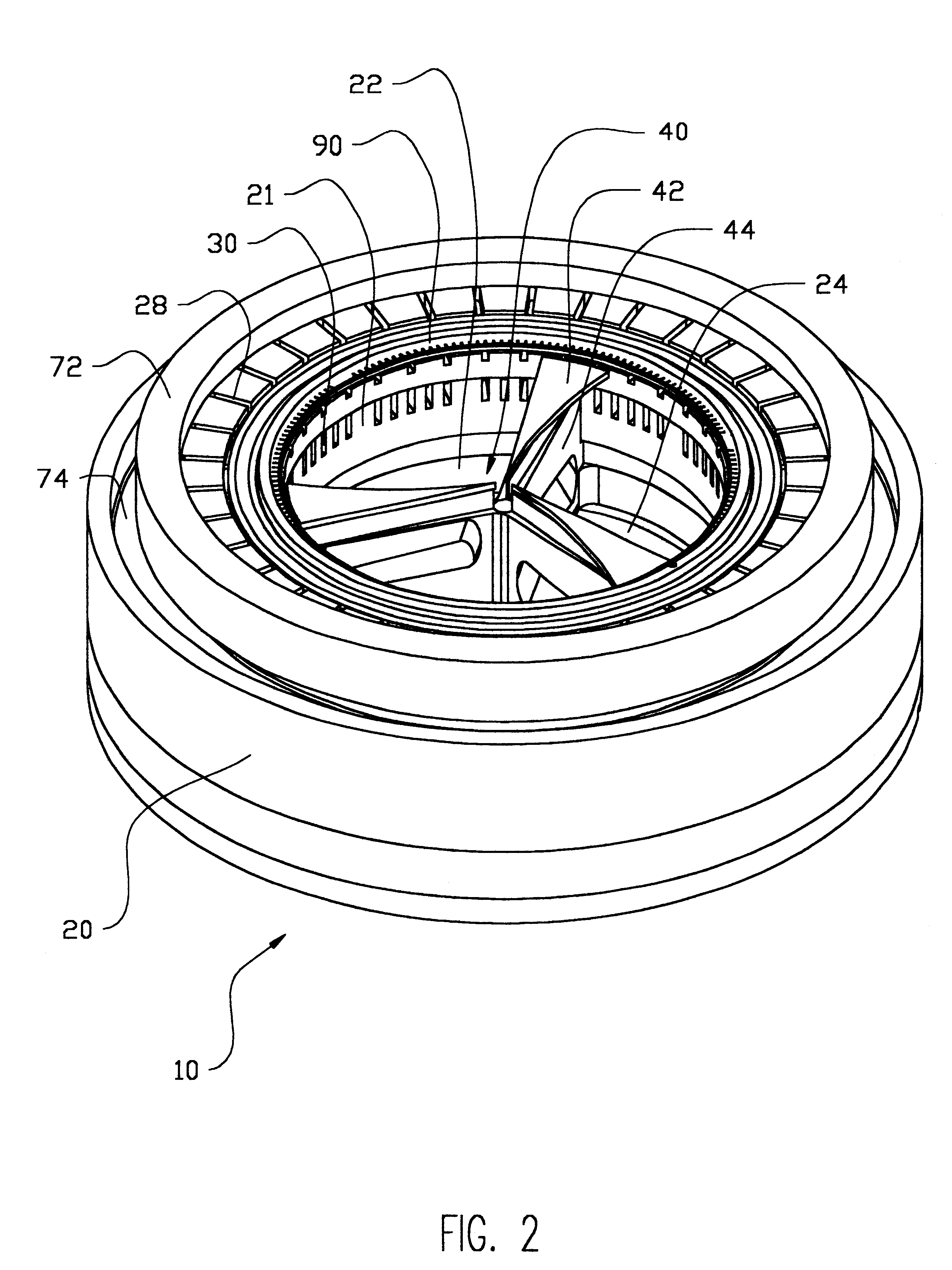
Referring to FIG. 1, the invention, as applied to the illustrative and important field of electroplating and the like, embodies a plurality of stacks of similar electroplating process chamber modules 10 that can be readily configured into an automated wafer processing cluster tool 12. In the embodiment shown, a plurality of vertically stacked process module frames 14 support the corresponding plurality of stacks of process modules 10. Externally visible are each of the process chamber bodies 20, more particularly shown on an enlarged scale in FIG. 2, and the process module cover 22. The process module frames 14 circumferentially surround the wafer handling robot 16 of well-known type such that the robot is able to insert wafers horizontally into and retrieve wafers horizontally from all process modules. A suitable wafer-handling robot for the purposes of this invention may, for example, be the Staubli Unimation RX-90 for this preferred embodiment of the invention. A conventional clu...


PUM

PropertyMeasurementUnit
Thicknessaaaaaaaaaa
Angleaaaaaaaaaa
Flow rateaaaaaaaaaa

Abstract

A novel method and apparatus of wet processing workpieces, such as electroplating semiconductor wafers and the like, that incorporates reciprocating processing fluid agitation to control fluid flow at the workpiece, and where electric fields are involved as in such electroplating, controlling the electric field distribution.

Description

The present invention relates to the control of fluid flow in the wet processing of the surfaces of workpieces in such applications as electroplating and the like, where electric fields may also be involved, being more particularly, though not exclusively, directed to the processing of substantially thin or planar workpieces such as silicon semiconductor wafers and the like, by the automatic and controlled processing application and removal of fluid from such surfaces, as well as more generally the control of wet processing of other types of workpiece surfaces including wet processing without electric fields, as later discussedWhile, as above indicated, the invention has general application and usefulness in various types of wet processing of a myriad of workpiece surfaces, the principal thrust of the preferred embodiment and particular advantageous use of the invention resides in the field of electroplating, and more specifically for such applications as the electroplating of thin ...

Claims


Application Information

Patent Timeline
IPC IPC(8): C25D7/12
CPCC25D17/001C25D7/123
Inventor KEIGLER, ARTHUR
Owner HERCULES TECH GROWTH CAPITAL
Why Eureka
Try Eureka