Organic electroluminescent device
a technology of electroluminescent devices and metals, which is applied in the direction of discharge tube luminescnet screens, natural mineral layered products, etc., can solve the problems of deformation under the influence of air, limited service life of el devices based on such metals, and inability to achieve the performance necessary for the above-mentioned applications, etc., and achieve satisfactory light output and good el efficiency
- Summary
- Abstract
- Description
- Claims
- Application Information
AI Technical Summary
Benefits of technology
Problems solved by technology
Method used
Image

Examples
exemplary embodiment 3
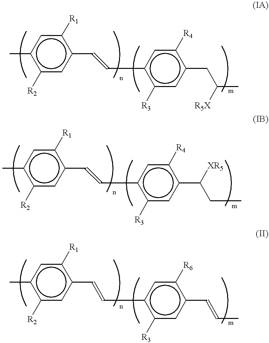
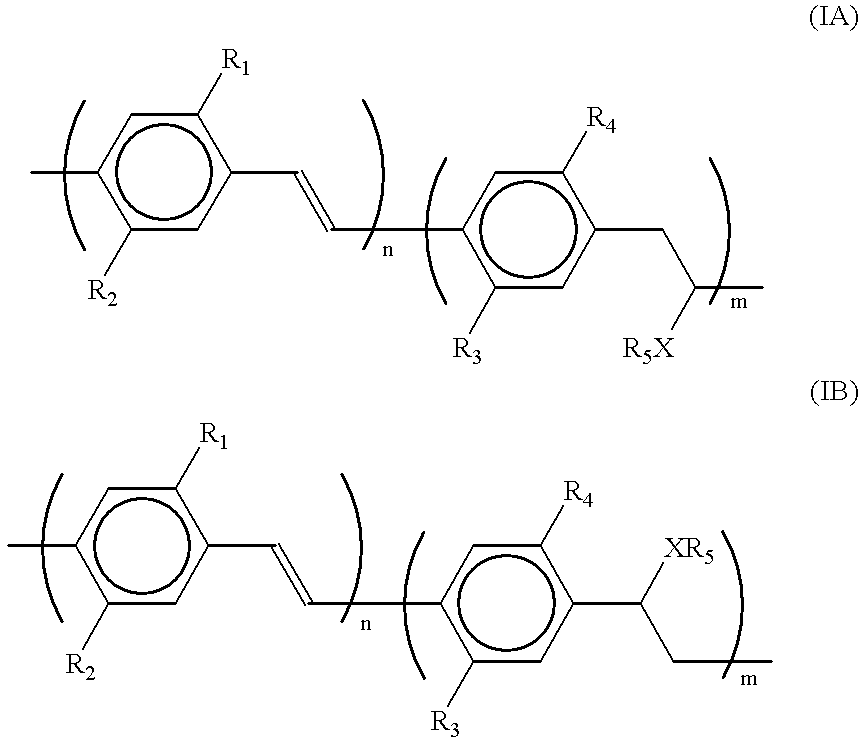
Exemplary embodiment 2 is repeated, with this difference that the polymer used is a polymer in accordance with formula (I), wherein R.sub.1 and R.sub.3 are equal to 3,7-dimethyloctyl, R.sub.2 and R.sub.4 are equal to methyl, R.sub.5 is equal to [--CH.sub.2 CH.sub.2 N(CH.sub.3).sub.3 ].sup.+ I.sup.- and m / (n+m)=0.04. The device exhibits a comparable performance, however, the light emitted is green and emission is observed from 3 V.
exemplary embodiment 4
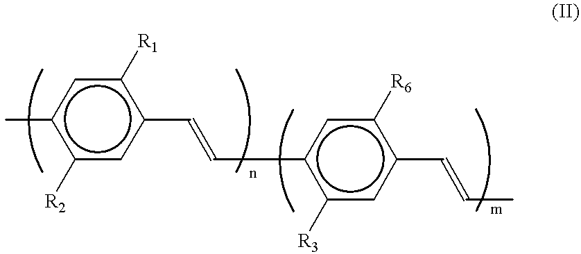
Exemplary embodiment 2 is repeated, with this difference that the polymer used is a polymer in accordance with formula (II), wherein R.sub.1 and R.sub.3 are equal to methoxy, R.sub.2 is equal to 3,7-dimethyloctyloxy, R.sub.6 is equal to [--CH.sub.2 CH.sub.2 N(CH.sub.3).sub.3 ].sup.+ I.sup.-, and m / (m+n) ranges from 0.01 to 0.25, which polymer is obtained in accordance with synthetic recipe 2. After activating for approximately 2 minutes at 15 V, the device thus manufactured has a luminance of 100 Cd / m.sup.2 at 5 V. The EL efficiency then amounts to 1%. Orange-coloured light is emitted, which is observed already at 2.5 V. The service life of the device is much better than that of corresponding devices in which polymers in accordance with formula (IA / IB) are used and amounts to more than 30 days under ambient conditions.
Comparable results are obtained with the polymer in which R.sub.3 and R.sub.6 have the above-mentioned meaning, R.sub.1 is H and R.sub.2 is 3-methoxyphenyl, which poly...
exemplary embodiment 5
Exemplary embodiment 4 is repeated, with this difference that the service life test is carried out by accommodating the device in a sealed glass container which is saturated with water vapour. The service life is shorter than that of devices exposed to air, yet it is still more than one week.
PUM
| Property | Measurement | Unit |
|---|---|---|
| work function | aaaaa | aaaaa |
| thicknesses | aaaaa | aaaaa |
| thicknesses | aaaaa | aaaaa |
Abstract
Description
Claims
Application Information