Composition and method for removing photoresist materials from electronic components

a technology of electronic components and materials, applied in the direction of cleaning using liquids, instruments, applications, etc., can solve the problem of high volume of undesirable liquid waste streams

Inactive Publication Date: 2002-06-11
LOS ALAMOS NATIONAL SECURITY
View PDF11 Cites 41 Cited by
  • Summary
  • Abstract
  • Description
  • Claims
  • Application Information

AI Technical Summary

Problems solved by technology

Use of any of these solvent mixtures produces high volumes of undesirable liquid waste streams.

Method used


Image

  • Composition and method for removing photoresist materials from electronic components
  • Composition and method for removing photoresist materials from electronic components
  • Composition and method for removing photoresist materials from electronic components

Examples


example i

For making the invention run described in this example, equipment was set up in the manner shown in the schematic of FIG. 2.

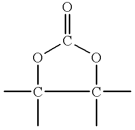
Carbon dioxide was used as the dense phase fluid and propylene carbonate was used as the dense phase fluid modifier for removing photoresist material from the silicon substrate of a semiconductor chip wafer.

A mixture of 5% propylene carbonate and 95% carbon dioxide supplied by Scott Specialty Gases, Inc., in a standard size A syphon cylinder was used as feed material for a propylene carbonate and carbon dioxide reservoir 11. The pressure in the syphon cylinder was approximately 900 psi at room temperature, which was sufficient to maintain the contents in liquid form.

The propylene carbonate and carbon dioxide reservoir 11 was connected by a conduit 13 to an ISCO.TM. 260D syringe pump 15 which was in turn connected by conduit 17 to a Whitey.TM. 304L-HDF4 1000 cc high pressure sample cylinder which served as a ballast tank 21. The conduit 17 between the syringe pu...

example ii

A set of runs were made for purposes of comparison of use of unmodified supercritical carbon dioxide, modifier alone, and combinations of supercritical carbon dioxide and modifier using varied temperature, pressure and contact conditions. The compositions and contact conditions of these runs are shown in Table I.

Runs 1 through 4 were comparison runs; Runs 5 through 12 were invention runs.

Runs 1, 2, and 4-12 were performed using an ISCO.TM. 260D syringe pump controlled with a series D controller. For Runs 5, 6 and 7, a larger scrub pump was also used in a separate step.

In Runs 1 and 2, 100% carbon dioxide was delivered by the pump to an ISCO.TM. SFX-2-10 supercritical fluid extractor.

In Runs 3 and 4, 100% propylene carbonate then 100% carbon dioxide was sequentially delivered by the pump to the ISCO.TM. SFX-2-10 supercritical fluid extractor.

In Runs 5, 6 and 7, a mixture of 5% propylene carbonate and 95% carbon dioxide, supplied by H.P. Gas Products, Inc., was delivered by the pump t...


PUM

PropertyMeasurementUnit
pressureaaaaaaaaaa
temperatureaaaaaaaaaa
pressureaaaaaaaaaa

Abstract

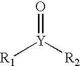
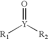
The invention is a combination of at least one dense phase fluid and at least one dense phase fluid modifier which can be used to contact substrates for electronic parts such as semiconductor wafers or chips to remove photoresist materials which are applied to the substrates during manufacture of the electronic parts. The dense phase fluid modifier is one selected from the group of cyclic, aliphatic or alicyclic compounds having the functional group:wherein Y is a carbon, oxygen, nitrogen, phosphorus or sulfur atom or a hydrocarbon group having from 1 to 10 carbon atoms, a halogen or halogenated hydrocarbon group having from 1 to 10 carbon atoms, silicon or a fluorinated silicon group; and wherein R1 and R2 can be the same or different substituents; and wherein, as in the case where X is nitrogen, R1 or R2 may not be present. The invention compositions generally are applied to the substrates in a pulsed fashion in order to remove the hard baked photoresist material remaining on the surface of the substrate after removal of soft baked photoresist material and etching of the barrier layer.

Description

This invention relates to use of dense phase fluids in combination with dense phase fluid modifiers as solvents for removal of polymers and photoresist materials used in the manufacture of semiconductor wafers or chips.During manufacture of integrated circuits, commonly referred to as semiconductor chips or microchips, several iterations of a photolithographic process are used. In this manufacturing process, dielectric, barrier or electrically conducting layers such as silicon dioxide, silicon nitride or metal is first deposited upon a substrate such as a silicon or gallium arsenide wafer by any of several suitable processes such as thermal oxidation, chemical vapor deposition, sputtering, ion implantation or vacuum evaporation.After formation or deposition of the dielectric, barrier or conducting layer, a photoresist material is applied to the wafer by any suitable means including, but not limited to, spinning of the wafer to distribute liquid photoresist evenly on the surface of t...

Claims


Application Information

Patent Timeline
Patent Type & Authority Patents(United States)
IPC IPC(8): B08B3/10B08B7/00C11D11/00C11D7/50G03F7/42H01L21/02H01L21/311C11D7/28C11D7/26C11D7/22C11D7/24C11D7/34
CPCB08B3/102B08B7/00H01L21/31133C11D7/50C11D7/5004C11D11/0047G03F7/422C11D7/24C11D7/266C11D7/267C11D7/34C11D7/28
Inventor DAVENHALL, LEISA B.RUBIN, JAMES B.
Owner LOS ALAMOS NATIONAL SECURITY
Why Eureka
Try Eureka