

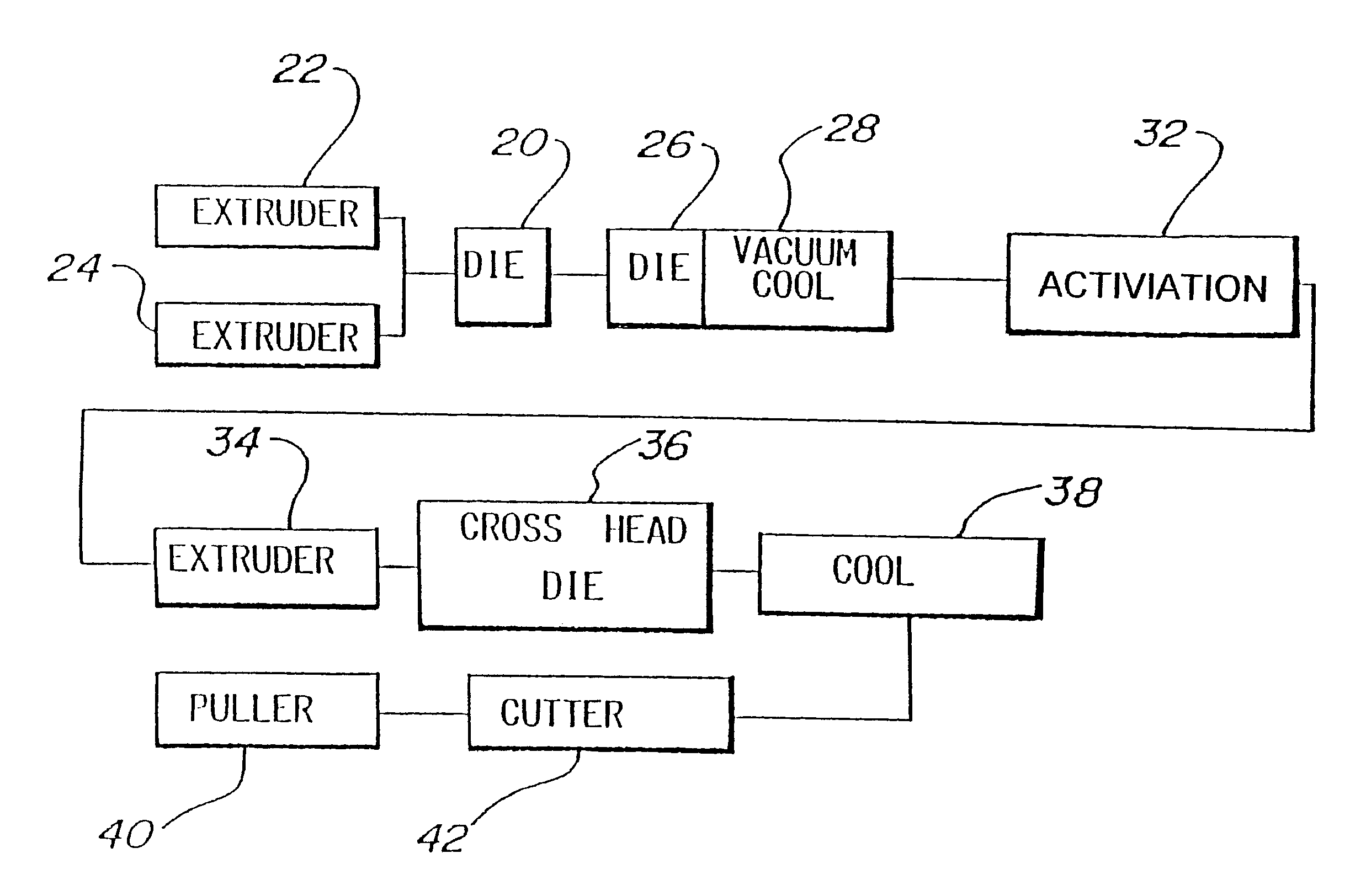
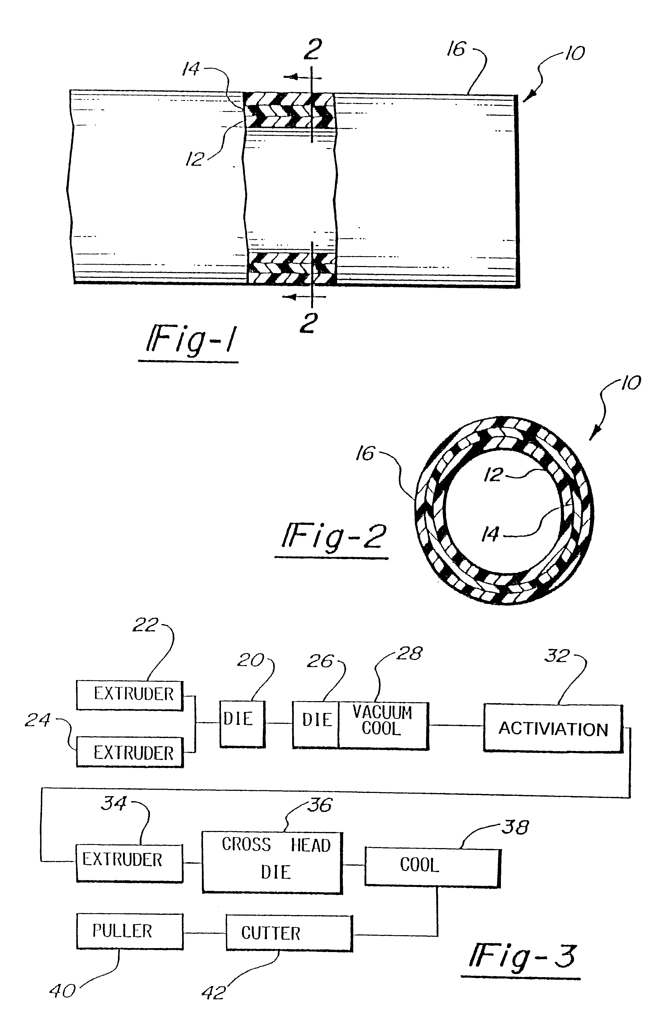
Fluoropolymer composite tube and method of preparation
a composite tube and fluorinated polymer technology, applied in the field of preparation of fluoropolymer composite tubes, can solve the problems of difficult use of fluorinated polymers and lack of irregular structure on polymer surfaces, and achieve the effect of increasing the strength of chemical bonds
- Summary
- Abstract
- Description
- Claims
- Application Information
AI Technical Summary
Benefits of technology
Problems solved by technology
Method used
Image

Examples
example 1
The surface energy of various treated fluoropolymers was tested. When a dyne solution is placed on a material surface and wets out, that indicates that the material has a higher surface energy than the dyne solution. If the drop "beads up," the material has a lower surface energy than the dyne solution. The use of the dyne solutions is a technique for determining the surface energy of materials. Various samples were prepared of fluoropolymer substrates. Each of the substrates were subjected to a dyne solution identified as ethyl Cello-Solve-Formamide (Trademark of Corotec of Connecticut, U.S.A.). The sample plaques were wiped clean with a dry cloth to remove surface contamination. Solvent was not used to avoid any surface effects from the residue. The dyne solution was applied in a single side-stroke of the brush to leave a 1 inch by 1 inch patch of solution. Measurements were taken on both treated and untreated samples. The values recorded represent solution which held in a continu...
example 2
Two 4".times.4".times.0.010" sheets of extruded ETFE (DuPont Tefzel7 200) were labeled as sample A and sample B. A slab of uncured ethylene / acrylic elastomer (DuPont VAMAC.RTM.) was placed over sample A and the two materials were clamped together for curing. Sample B was exposed for approximately 5 seconds to a charged gaseous atmosphere as previously described and then combined with a VAMAC.RTM. layer and clamped as with sample A. Both samples were placed in a circulating air oven at 180.degree. C. for 30 minutes to cure the thermosetting layer. Samples were then removed and allowed to cool at room temperature for 30 minutes. Samples were removed from clamps and cut into strips using an ASTM .chi.".times.6" die and Arbor press. Six strips from each sample were tested for lap shear strength by separating the layers at the ends of the strip, leaving a 3 0 mm section of joined material at the center. Each layer of the strip was attached to an opposing tensile machine fixture and the s...
example 3
Two 1" diameter tubes of extruded ETFE were labeled sample A and sample B. Two propane torches were adjusted to produce a 6" flame, and held by hand so that only the tip of the flame contacted the ETFE surface of sample B. The torches were positioned on opposite sides of sample B approximately 1.5' prior to sample B entering the mixed gas plasma chamber. Sample A entered the chamber without prior flame exposure. Subsequent to activation, a layer of nylon was extruded around the fluoropolymer tube. The samples were then tested for bond strength by separating the ETFE and Nylon layers and then pulling these layers apart on a tensile machine while recording force required to separate. These tests showed a 235% increase in maximum load (highest reading of force obtained during test), and a 387% increase in average load with the addition of the flame-treatment. Values obtained for Work (load.times.length pulled) could not be compared directly as the bond strength of the flame-treated sam...
PUM
| Property | Measurement | Unit |
|---|---|---|
| Surface state | aaaaa | aaaaa |
Abstract
Description
Claims
Application Information