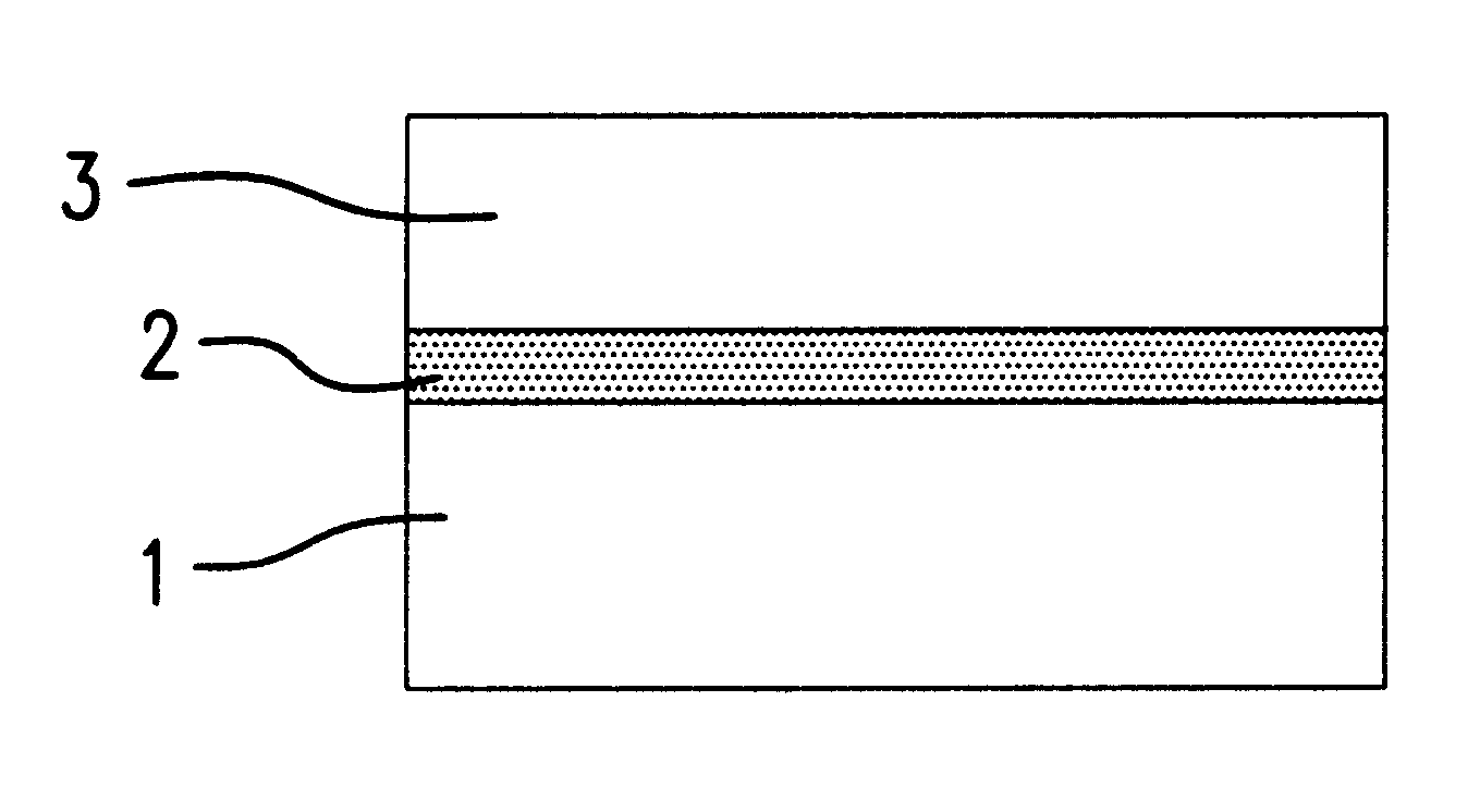
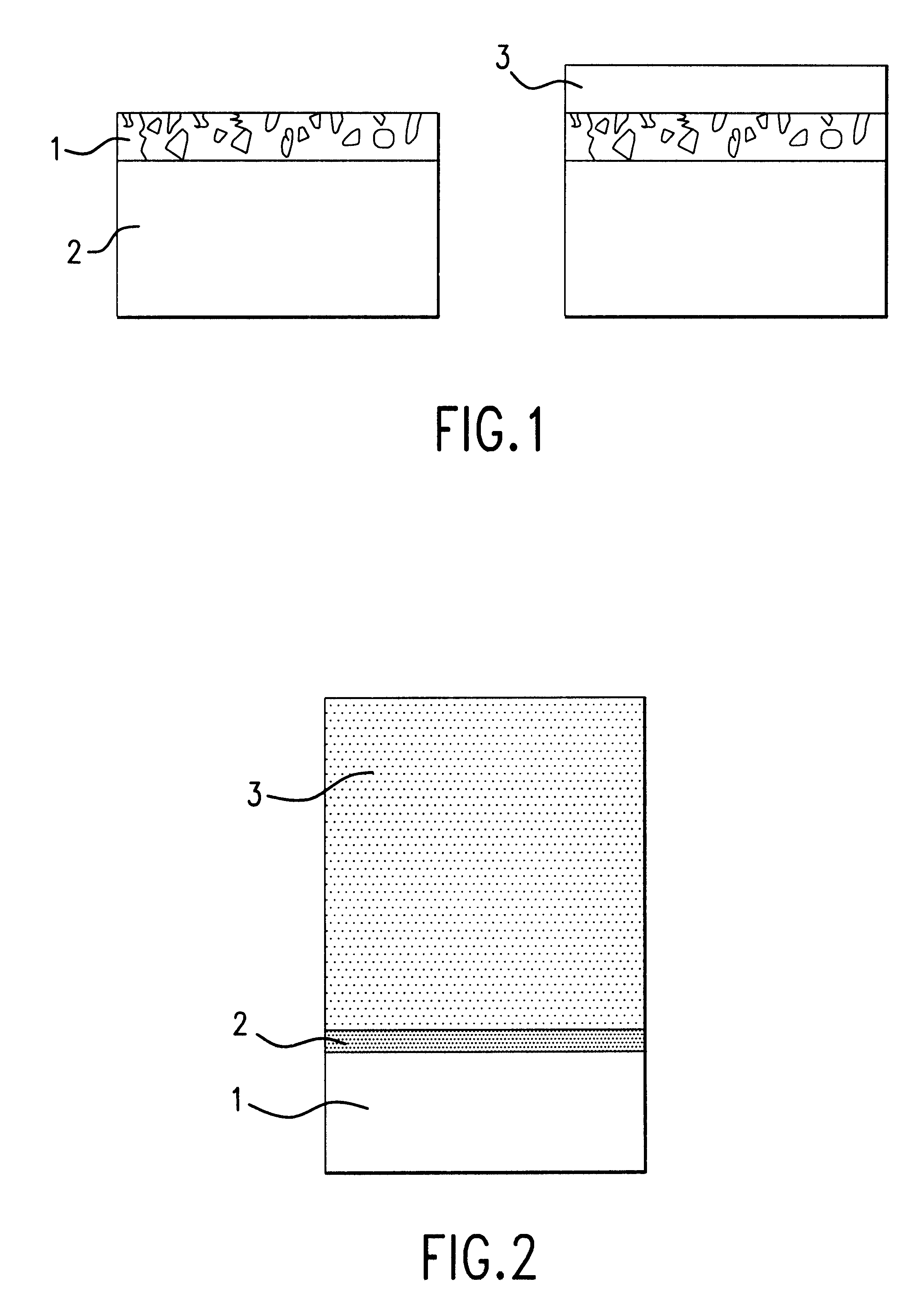
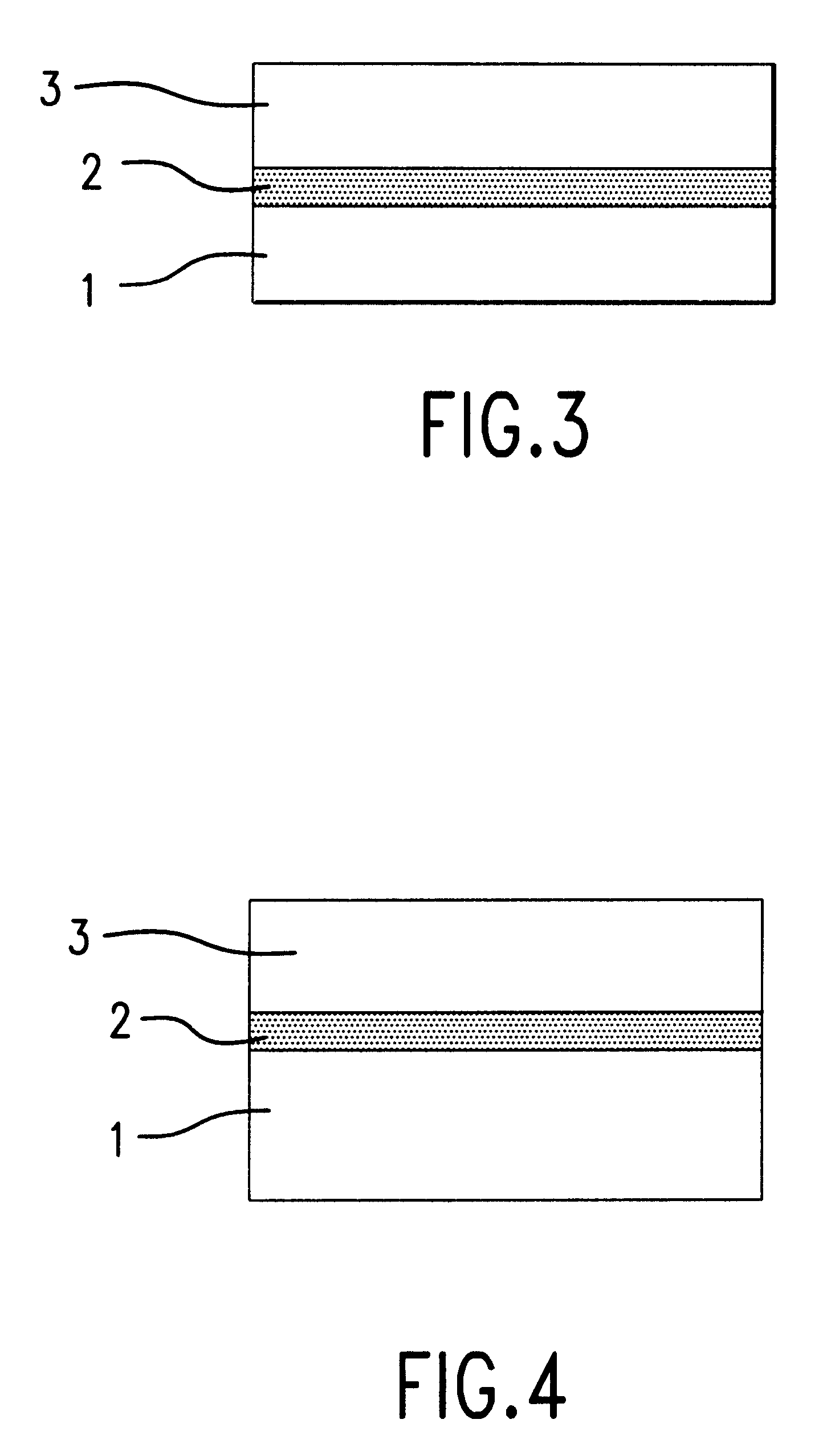
Method of crystal growth and resulted structures
a crystal growth and crystal growth technology, applied in the direction of crystal growth process, polycrystalline material growth, after-treatment details, etc., can solve the problems of limiting the use of the whole area of the wafer for device structures, and affecting the quality of the original material
- Summary
- Abstract
- Description
- Claims
- Application Information
AI Technical Summary
Benefits of technology
Problems solved by technology
Method used
Image

Examples
example 2
Another example is a fabrication of a Silicon Carbide monocrystal layer. Monocrystal wafer to be processed in this case was commercial 4H--SiC wafer. Porous monocrystal SiC layer was developed by surface anodization of the wafer in 4%-aqueous solution of HF. The process was carried out without UV illumination at 15 mA / cm.sup.2 current density during 5 minutes, which yielded the thickness of porous layer was about 2.5 microns. After the formation of porous SiC, the wafer was carefully cleaned to remove any residual chemicals.
Epitaxial monocrystal SiC layer was grown on porous layer using the chemical vapor deposition (CVD) method in a horizontal, cold-wall, atmospheric pressure reactor. The equipment of CVD technique used is known and has been adequately described in S. E. Saddow, M. S. Mazzola, S. V. Rendakova, V. A. Dmitriev, Material Science and Engineering B, B61-62, 158 (1999). The growth conditions were a Si to C ratio of 0.3, a growth temperature of approximately 1580.degree. ...
example 3
Another example is related to bulk crystal SiC growth by sublimation. 6H--SiC porous material was fabricated from 2 inch diameter 6H--SiC single crystal wafer. The wafer had (0001)Si face polished. On this face, 5 microns thick porous single crystal SiC layer was formed by anodization. The wafer having porous SiC layer was placed in high-temperature furnace and heated up to 2200.degree. C. Bulk 6H--SiC crystal was grown by a standard growth procedure using sublimation growth method. After the growth, the crystal was removed from the furnace and the porous SiC layer was removed by polishing. SiC wafers fabricated by slicing and polishing from the bulk crystal had less defect density than SiC wafers grown on standard substrates.
PUM
| Property | Measurement | Unit |
|---|---|---|
| temperature | aaaaa | aaaaa |
| size | aaaaa | aaaaa |
| thickness | aaaaa | aaaaa |
Abstract
Description
Claims
Application Information
 - Generate Ideas
- Intellectual Property
- Life Sciences
- Materials
- Tech Scout
- Unparalleled Data Quality
- Higher Quality Content
- 60% Fewer Hallucinations
Browse by: Latest US Patents, China's latest patents, Technical Efficacy Thesaurus, Application Domain, Technology Topic, Popular Technical Reports.
© 2025 PatSnap. All rights reserved.Legal|Privacy policy|Modern Slavery Act Transparency Statement|Sitemap|About US| Contact US: help@patsnap.com