Optical element equipped with lanthanum fluoride film

a technology of lanthanum fluoride and optical elements, applied in the field of optical elements, can solve the problems of fluorine deficiency, complex control of reaction, fluorine deficiency in vapor deposition film,

Inactive Publication Date: 2004-10-26
NIKON CORP
View PDF16 Cites 4 Cited by
  • Summary
  • Abstract
  • Description
  • Claims
  • Application Information

AI Technical Summary

Benefits of technology

According to a second aspect of the present invention, there is provided an optical element comprising an optical substrate; an underlayer which is formed of one of calcium fluoride, barium fluoride, and strontium fluoride; and a lanthanum fluoride film which is formed directly on the underlayer. When a plane of the underlayer, on which the lanthanum fluoride film is formed, is a (111) plane or a plane inclined by an angle within .+-.30 degrees from the (111) plane, the crystal of lanthanum fluoride film may be grown in C-axis orientation on the underlayer. Since the lanthanum fluoride film is dense and has a small surface area, it scarcely involves the oxidation and hydroxylation areas as well as the structural defect. Accordingly, it is possible to reduce the optical loss of the optical element in the vacuum ultraviolet region. Therefore, the optical elements according to the first and second aspects of the present invention are preferably usable as an optical element equipped with an antireflection film in the vacuum ultraviolet region.
According to a third aspect of the present invention, there is provided an exposure apparatus for exposing a substrate with an image of a pattern formed on a mask, the exposure apparatus comprising an illumination optical system which illuminates the mask with a vacuum ultraviolet light beam; and a projection optical system which includes the optical element according to the first or second aspect and which projects the image of the pattern onto the substrate. According to a fourth aspect of the present invention, there is provided an exposure apparatus for exposing a substrate with an image of a pattern formed on a mask, the exposure apparatus comprising an illumination optical system which includes the optical element according to the first or second aspect and which illuminates the mask with a vacuum ultraviolet light beam; and a projection optical system which projects the image of the pattern onto the substrate. According to the exposure apparatuses in accordance with the third and fourth aspects, the illumination optical system or the projection optical system includes the optical element according to the present invention. Therefore, it is possible to decrease the optical loss in the illumination optical system or the projection optical system with respect to the exposure light beam, especially with respect to the light beam in the vacuum ultraviolet region. Further, it is possible to efficiently introduce the exposure light beam onto the substrate. As a result, it is possible to improve the throughput of the exposure apparatus in which the operation of the exposure apparatus would be otherwise interrupted or restricted due to the maintenance including, for example, the cleaning and the exchange of the optical element disposed in the illumination optical system or the projection optical system.
According to a fifth aspect of the present invention, there is provided a method for producing an optical element, comprising preparing an optical substrate which is formed of one of calcium fluoride, barium fluoride, and strontium fluoride and which plane is a (111) plane or a plane inclined by an angle within .+-.30 degrees from the (111) plane; and forming a lanthanum fluoride film on the plane of the optical substrate. According to a sixth aspect of the present invention, there is provided a method for producing an optical element, comprising forming an underlayer composed of one of calcium fluoride, barium fluoride, and strontium fluoride on an optical substrate while heating the optical substrate so that a (111) plane or a plane inclined by an angle within .+-.30 degrees from the (111) plane appears; and forming a lanthanum fluoride film on the underlayer. According to the production methods in accordance with the fifth and the sixth aspects, the lanthanum fluoride film undergoes crystal growth while being subjected to C-axis orientation from the (111) plane or the plane inclined by the angle within .+-.30 degrees from the (111) plane of calcium fluoride, barium fluoride, or strontium fluoride. Accordingly, it is possible to obtain the lanthanum fluoride film which is dense, which has a small surface area, and which scarcely involves the oxidation and hydroxylation areas as well as the structural defect. Therefore, it is possible to obtain the optical element in which the optical loss is reduced in the vacuum ultraviolet region.

Problems solved by technology

Fluorine is deficient as compared with the stoichiometric composition in the fluoride thin film produced by any film formation technique other than the resistance heating type vacuum deposition method.
Therefore, the fluorine deficiency occurs in the vapor deposition film.
However, it is complicated to control the reaction, and a film, which is based on the stoichiometric composition, is not necessarily obtained with ease.
Therefore, the fluoride thin film has such a drawback that the film is porous and it has a large surface area, as compared with the single crystals and the bulk polycrystals as well as the films produced by the other film formation methods.
This drawback results from the fact that the substrate (fluoride optical element) has the low temperature.
Further, the shape of the lens surface, which has been strictly finished, is also changed, and the intended function as the optical element is consequently lost.
However, when the substrate temperature is relatively low, then it is impossible for the adsorbed particles to obtain the energy sufficient to make the movement on the surface, and the particles are immediately solidified after the adsorption.
Therefore, the structure of the consequently formed film is a coarse columnar-shaped structure, and the structural irregularity is frequently caused as well.
However, the film, which is produced by the resistance heating type vacuum deposition method, has the columnar-shaped structure, the film is porous, and the film has a large surface area.
However, the fluorine deficiency occurs in the vicinity of the surface exposed to the atmospheric air as a result of the chemical reaction with water in the atmospheric air to cause the oxidation and the hydroxylation.
Therefore, the optical loss is extremely large as compared with MgF.sub.2.
Therefore, the frequency of the exchange of optical element parts has been inevitably increased.

Method used


Image

  • Optical element equipped with lanthanum fluoride film
  • Optical element equipped with lanthanum fluoride film
  • Optical element equipped with lanthanum fluoride film

Examples


first embodiment

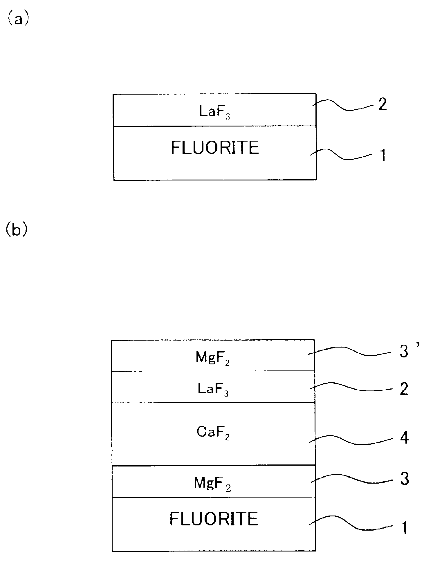
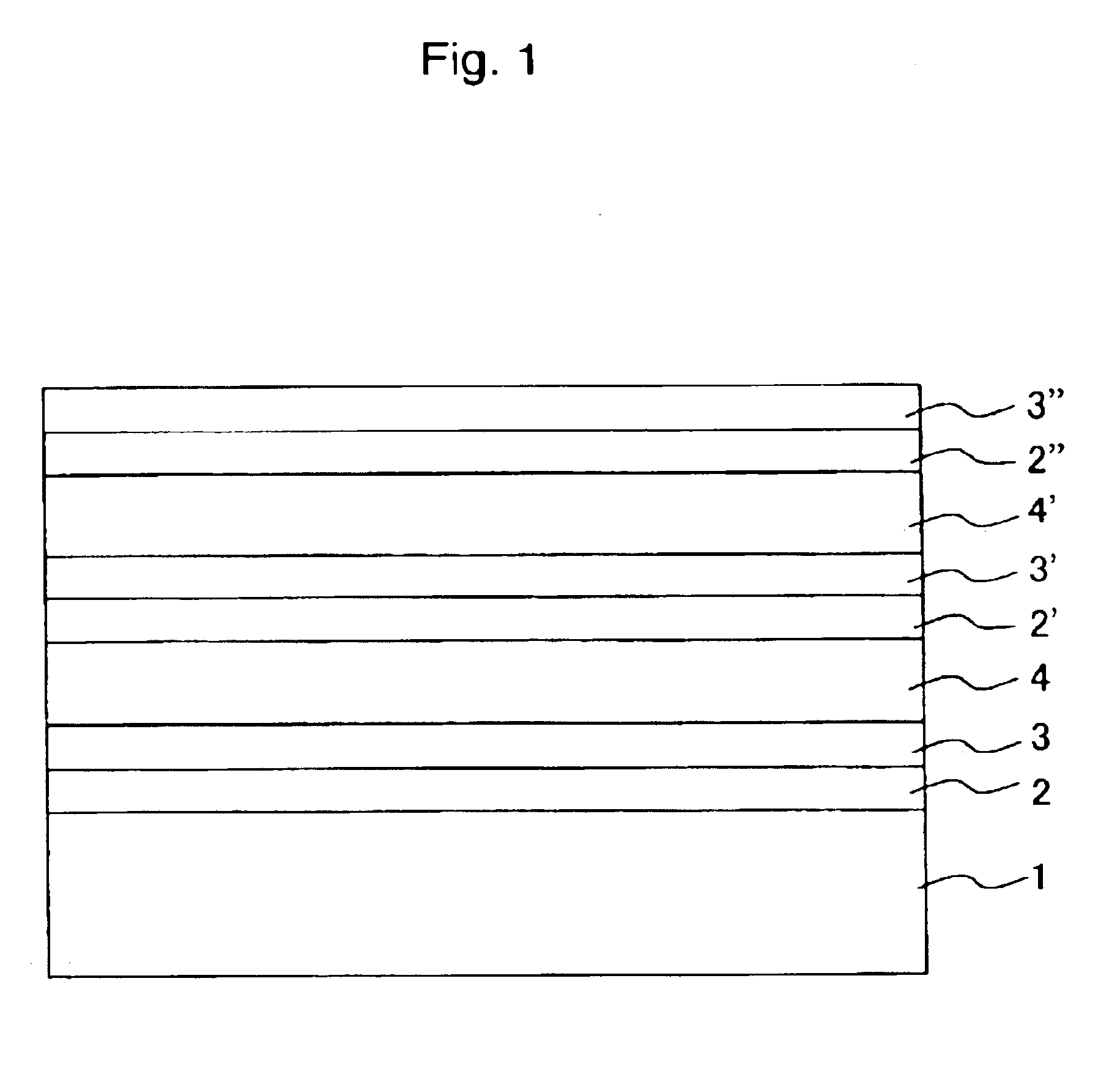
A fluorite (CaF.sub.2) single crystal substrate was prepared as a material for an optical element for the vacuum ultraviolet light. At first, the X-ray diffraction was used to measure the direction of the fluorite single crystal substrate in which the (111) crystal plane is positioned. The substrate was cleaved in parallel to the measured (111) crystal plane to expose the (111) crystal plane. Subsequently, an LaF.sub.3 film was formed to have a film thickness of 500 nm on the exposed (111) crystal plane by means of the resistance heating type vacuum deposition method as described below. Crystal grains of lanthanum fluoride, which were used as a raw material, were introduced into a vapor deposition boat made of molybdenum. The substrate, on which the (111) crystal plane was exposed, was arranged at a position opposed to the vapor deposition boat. Subsequently, the raw material fluoride crystals were evaporated by applying the electricity and heating the vapor deposition boat while he...

second embodiment

A sample was manufactured, in which an LaF.sub.3 film was formed on a fluorite single crystal substrate in the same manner as in the first embodiment except that a plane inclined by 15 degrees from the (111) crystal plane of the fluorite single crystal substrate was exposed by the cleavage, and the LaF.sub.3 film was formed thereon. The X-ray diffraction analysis was performed for this sample. As a result, when the film formation plane of the fluorite as the underlying base was inclined by 15 degrees from the (111) plane, the (00L) plane of the LaF.sub.3 film grown on the film formation plane was also precisely inclined by 15 degrees. In other words, the LaF.sub.3 film was subjected to the C-axis orientation in the direction inclined by 15 degrees from the film formation plane. That is, it is appreciated that the LaF.sub.3 film is progressively grown in accordance with the crystalline orientation of CaF.sub.2 which serves as the underlying base in every sense not in accordance with ...

first modified embodiment

A sample was manufactured in the same manner as in the first embodiment except that the fluorite substrate was replaced with an SrF.sub.2 substrate. The sample was evaluated in accordance with the method described above. As a result, it was revealed that an LaF.sub.3 film formed on a (111) plane of the SrF.sub.2 substrate was subjected to the crystal growth in the C-axis direction, and LaF.sub.3 film, which was dense equivalently to the bulk, was formed, probably for the following reason. That is, it is considered that the crystalline structure of SrF.sub.2 resides in the fluorite type cubic system which is the same as that of the fluoride, and the lattice constant is represented as a=0.57996 nm which is close to the lattice constant of the fluorite.


PUM

PropertyMeasurementUnit
temperatureaaaaaaaaaa
wavelengthsaaaaaaaaaa
wavelengthaaaaaaaaaa

Abstract

An optical element of the present invention comprises a fluorite substrate 1, and a lanthanum fluoride film 2 formed directly on the substrate 1. The substrate 1, on which the lanthanum fluoride film 2 is formed, has a plane which is a (111) plane or a plane inclined by an angle within ±30 degrees, preferably within 15 degrees from the (111) plane. Therefore, the lanthanum fluoride film undergoes the crystal growth subjected to the C-axis orientation on the optical substrate. Since the lanthanum fluoride film is dense and has a small surface area, it scarcely involves the oxidation and hydroxylation areas as well as the structural defect. Therefore, it is possible to reduce the optical loss of the optical element in the vacuum ultraviolet region.

Description

CROSS-REFERENCEThis application is a Continuation Application of International Application No. PCT / JP02 / 07266 which was filed on Jul. 17, 2002 claiming the conventional priority of Japanese patent Application No. 2001-218045 filed on Jul. 18, 2001.1. Field of the InventionThe present invention relates to an optical element having a multilayer film which minimally absorbs the light in the vacuum ultraviolet region and to an exposure apparatus provided with the optical element.2. Description of the Related ArtThe fluoride material has such an excellent optical characteristic that the material is transparent over a wide light wavelength range from the infrared to the vacuum ultraviolet region. In particular, almost all of oxide materials are opaque at wavelengths of not more than 180 nm, while a large number of fluoride materials are transparent. Therefore, the fluoride is necessary and indispensable especially for optical thin films and optical element materials to be used for the vac...

Claims


Application Information

Patent Timeline
Patent Type & Authority Patents(United States)
IPC IPC(8): B32B18/00C04B35/515C04B35/553C23C14/06G02B1/10G02B5/28G02B1/02G03F7/20
CPCC04B35/553G03F7/70958G02B1/02G02B1/115C23C14/0694C04B2235/723C04B2235/76G02B5/283
Inventor TAKI, YUSUKE
Owner NIKON CORP
Why Eureka
Try Eureka