

Glass forming mold
a mold and glass technology, applied in the field of glass forming molds, can solve the problems of deterioration of glass product quality, surface roughness, surface precision, etc., of the mold surface, and the chromium coating film surface will be corroded at high temperature, so as to prevent the diffusion of oxygen in air into the mold surface, the effect of high adhesive strength and excellent stability
- Summary
- Abstract
- Description
- Claims
- Application Information
AI Technical Summary
Benefits of technology
Problems solved by technology
Method used
Image

Examples
examples 1 to 9 (examples 1 , 2 , 6 and 9
Examples 1 to 9 (Examples 1, 2, 6 and 9 are Comparative Examples, and Examples 3 to 5, 7 and 8 are Examples of the present invention) and the measuring methods are as follows.
1) Si deposition amount: Using a fluorescent X-ray apparatus (RIX 3000, manufactured by Rigaku Denki K.K.), the Si deposition amount within a measured range of 3 cm in diameter of a silicon oxide film, was calculated.
2) Chromium concentration: A powdery substance deposited on the mold was dissolved in pure water, and using an inductively coupled plasma emission spectrochemical analyzer (SPS4000, manufactured by SII), the concentration of chromium contained in the powdery substance was measured by an emission spectrochemical analysis.
3) Surface roughness: Whether or not the surface roughness of the mold is uniform, was visually judged. Symbol “◯” means “uniform” and symbol “X” means “non-uniform”. For the practical purpose, “◯” is preferred.
4) Crystal orientation (peak intensity): Using an X-ray diffraction appa...
example 1
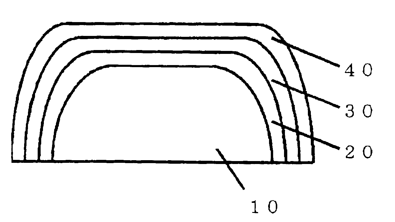
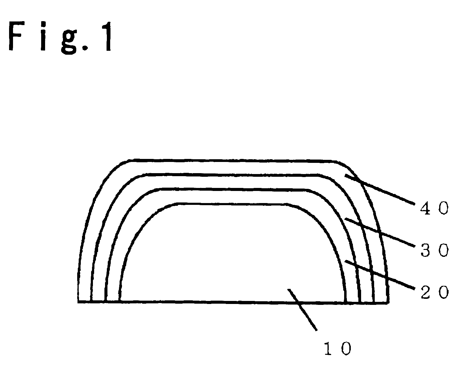
By means of an electrolytic plating method, a chromium-plated coating film having a thickness of 20 μm, was formed on the molding surface of a mold (for a panel of 29 inches) for forming a panel glass for a cathode ray tube, made of SUS420J2 (JIS-G4303) as the base material of the mold. Using such a mold, forming of a panel glass for a cathode ray tube was carried out for 96 hours, whereupon the concentration of chromium in the powdery substance deposited on the mold, and the surface roughness of the mold, were measured. The results are shown in Table 1.
examples 2 to 6
By means of an electrolytic plating method, a chromium-plated coating film having a thickness of 20 μm, was formed on the molding surface of a mold for forming a panel glass for a cathode ray tube, made of SUS420J2 as the base material of the mold. A silicon coating fluid was prepared by adjusting with water so that silicone emulsion SH-490 (manufactured by Toray Dow Corning Co., Ltd.) would be at each concentration in the coating fluid, as identified in Table 1. Such a silicon coating fluid was coated on the surface of the above chromium-plated coating film by means of a spraying method and then heated in air at a temperature of 500° C. for 4 hours, to form a chromium oxide film on the surface of the chromium-plated coating film, and further, a silicon oxide film was formed on the chromium-oxide film. The Si deposition amount of the above silicon oxide film was measured, and then, by means of the above-mentioned mold, forming of a panel glass for a cathode ray tube was carried out ...
PUM
| Property | Measurement | Unit |
|---|---|---|
| Thickness | aaaaa | aaaaa |
| Mass | aaaaa | aaaaa |
Abstract
Description
Claims
Application Information