In-situ method and composition for repairing a thermal barrier coating

a thermal barrier and in-situ technology, applied in the field of thermal barrier coatings, can solve the problems of high temperature corresponding increase in the durability of the components of the turbine, and insufficient mechanical properties, etc., to achieve the effect of avoiding disassembly, masking and over-spraying problems

Inactive Publication Date: 2005-04-05
GENERAL ELECTRIC CO
View PDF6 Cites 44 Cited by
  • Summary
  • Abstract
  • Description
  • Claims
  • Application Information

AI Technical Summary

Benefits of technology

In various embodiments, the present invention provides engineered particle distributions of fine and coarse yttria-stabilized zirconia (zirconium oxide) (YSZ) particles that are suspended in an organic binder including, for example, denatured ethanol, a polyalkylene glycol monobutyl ether and a silicone resin. The composition is tailored for a rheology that may be applied as a paste or putty to localized spalled areas of the thermal barrier coating (TBC) of a component of a turbine or the like. After application, the paste is dried and cured at low temperatures, attaining a tensile strength comparable to that of the surrounding TBC. Upon heating to operating temperatures, the TBC patch retains its mechanical strength and erosion resistance. This in-situ method alleviates the disassembly, masking and over-spraying problems associated with conventional TBC repair methods.

Problems solved by technology

However, as operating temperatures increase, the high-temperature durability of the components of the turbine must correspondingly increase.
Nonetheless, when used to form components of the turbine, such as combustor liners, augmentor hardware, shrouds and high and low-pressure nozzles and blades, the superalloys are often susceptible to damage by oxidation and hot corrosion attack and may not retain adequate mechanical properties.
However, localized spallation of a TBC may occasionally occur during the manufacturing process, regardless of the technique utilized, due to surface contamination, handling damage or the like.
The latter requirement is particularly demanding due to the different coefficients of thermal expansion between the ceramic materials and the superalloy substrates that they protect.
The service life of a TBC is typically limited by a spallation event brought on by thermal fatigue, contaminants present during the coating process, contact during turbine manufacture / assembly / operation, erosion, metallurgical issues, etc.
Accordingly, a significant challenge has been to obtain a more adherent ceramic layer that is less susceptible to spalling when subjected to thermal cycling and the like.
Though significant advances have been made, there is the inevitable requirement to repair components whose TBCs have spalled.
Grit-blasting, however, is a time-consuming, labor-intensive, expensive process and often erodes the surface beneath the coating.
With repetitive use, grit-blasting may eventually destroy the component.
The use of an alkaline or caustic solution to remove a TBC is also less than ideal, since the process requires the use of an autoclave operating at high temperatures and pressures.
Consequently, conventional repair methods are time-consuming, labor-intensive and expensive, and may be difficult to perform on components with complex geometries, such as airfoils and shrouds.
Thus, masking and over-spraying problems arise and time, effort and money are wasted.
In the case of large power-generation turbines, completely halting power generation for an extended period of time in order to remove components whose TBCs have suffered only localized spallation is not economically desirable.
A judgment is then made as to the risk of damage to the turbine due to the reduced thermal protection of the component, which if excessive may lead to catastrophic failure of the component.
If the decision is made to continue operation, the spalled component must typically be scrapped at the end of operation because of the thermal damage inflicted while operating the component without complete TBC coverage.
While providing a TBC patch with a relatively high thermal expansion coefficient and thermal stability (melting point), along with a relatively low thermal conductivity, this method provides relatively low erosion resistance due to the use of the hollow spheres of zirconia.

Method used


Image

  • In-situ method and composition for repairing a thermal barrier coating
  • In-situ method and composition for repairing a thermal barrier coating
  • In-situ method and composition for repairing a thermal barrier coating

Examples


Embodiment Construction

The present invention is directed to components protected by thermal barrier coatings (TBCs) for operation within environments characterized by relatively high temperatures, and therefore subjected to severe thermal stresses. Such components include those used in gas turbine engines and the like.

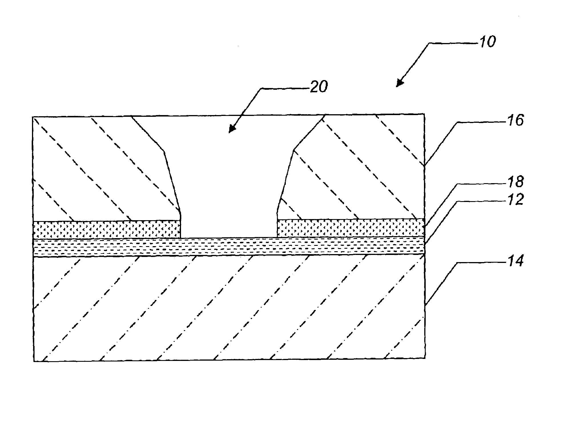
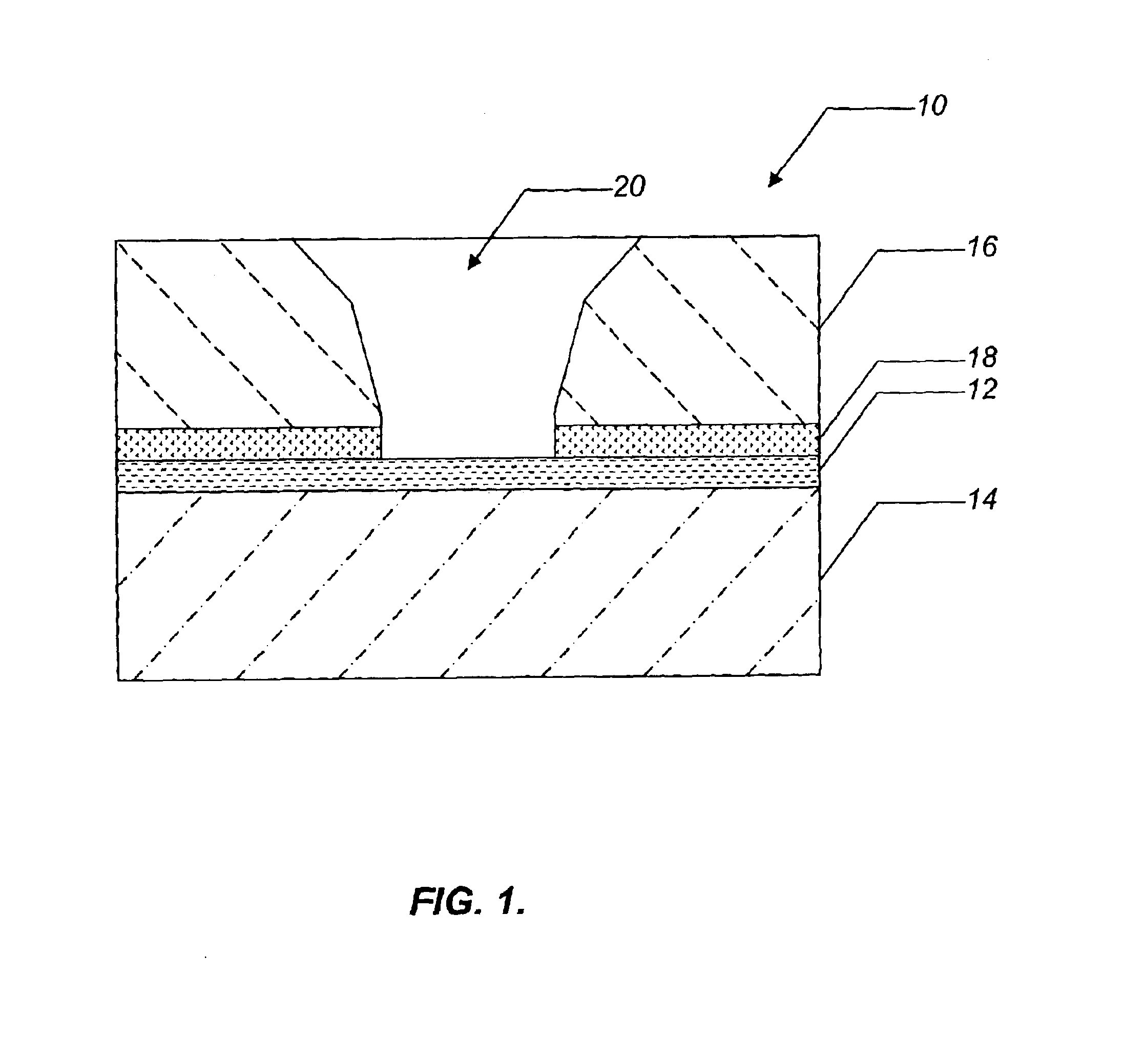
Referring to FIG. 1, a typical TBC system 10 includes a bond coating 12 deposited on the surface of a component 14. A ceramic layer 16 is deposited on the surface of the bond coating 12 and acts as the TBC. The component 14 may be formed from a nickel, cobalt or iron-based superalloy or the like. The bond coating 12 may be formed from a metallic oxidation-resistant material, so as to protect the underlying component 14 from oxidation and enable the ceramic layer 16 to more effectively adhere to the component 14. Suitable bond coatings 12 include MCrAlX overlay coatings (where M is iron, nickel and / or cobalt and X is yttrium or another rare earth element) and diffusion aluminide coatings. Fol...


PUM

PropertyMeasurementUnit
temperatureaaaaaaaaaa
diameteraaaaaaaaaa
diameteraaaaaaaaaa

Abstract

An in-situ method for repairing a thermal barrier coating deposited on a component that has suffered localized spallation including depositing a ceramic paste on a surface area of the component exposed by the localized spallation, the ceramic paste including a ceramic material in a binder material, the ceramic material including solid zirconia particles, the binder material including a silicone compound. The method also including heating the binder material to yield a repair coating that covers the surface area of the component, the silicone compound promoting the bonding of the solid zirconia particles.

Description

FIELD OF THE INVENTIONThe present invention relates generally to thermal barrier coatings for components exposed to high temperatures, such as components exposed to the hostile thermal environment of a gas turbine engine or the like. More specifically, the present invention relates to methods and compositions for repairing a thermal barrier coating that has suffered localized spallation.BACKGROUND OF THE INVENTIONHigher operating temperatures for gas turbine engines and the like are continuously sought in order to increase their efficiency. However, as operating temperatures increase, the high-temperature durability of the components of the turbine must correspondingly increase. Significant advances in high-temperature capabilities have been achieved through the formulation of nickel, cobalt and iron-based superalloys. These superalloys may be designed to withstand temperatures in the range of about 1000 to 1100 degrees C. or higher. Nonetheless, when used to form components of the ...

Claims


Application Information

Patent Timeline
Patent Type & Authority Patents(United States)
IPC IPC(8): C04B41/45C04B41/50C04B41/87C23C24/08C23C26/00C23C24/00F01D5/28C04B35/48C23C4/10F01D25/00F02C7/00
CPCC04B35/481C04B41/009C23C26/00C04B41/5042C04B41/87C23C24/08C04B41/4535C04B41/4554C04B41/5024C04B35/48F05C2253/12F05C2203/0895F05B2230/90F05B2230/80C04B2235/3244C04B2235/483C04B2235/5436C04B35/6263C04B2235/3225C04B2235/3246C04B2235/5445C04B2235/5472
Inventor RUUD, JAMES A.JANORA, KEVIN H.
Owner GENERAL ELECTRIC CO
Why Eureka
Try Eureka