Bio electron microscope and observation method of specimen

a technology of electron microscope and specimen, which is applied in the field of electron microscope, can solve the problems of insufficient specimen preparation function of electron microscope, difficult to provide image contrast, and inability to prepare specimens, etc., and achieves high contrast, low damage, and high-accuracy image analysis.

Inactive Publication Date: 2005-04-05
HITACHI HIGH-TECH CORP +1
View PDF3 Cites 104 Cited by
  • Summary
  • Abstract
  • Description
  • Claims
  • Application Information

AI Technical Summary

Benefits of technology

In view of the foregoing problems, an object of the present invention is to realize a bio electron microscope and an observation method which can

Problems solved by technology

The reason why staining is needed is that since a main element constituting a living body are light elements such as hydrogen, oxygen, carbon and nitrogen, those scattering factors to an electron beam and its difference between the elements are small so that image contrast is very hard to provide.
The electron microscope is not equipped with functions of specimen preparation such as extraction, purification, concentration and staining to observe a specimen by the electron microscope, and of analyzing the species of virus and a protein three-dimensional structure from a photographed image.
The bio specimen observed by the transmission electron microscope is susceptible to damage by electron irradiation.
When an electron beam having an accelerating voltage of 100-120 keV is irradiated onto a specimen of a tissue of such structure, damage such as deformation, decom

Method used


Image

  • Bio electron microscope and observation method of specimen
  • Bio electron microscope and observation method of specimen
  • Bio electron microscope and observation method of specimen

Examples


Embodiment Construction

An embodiment of the present invention will be described below.

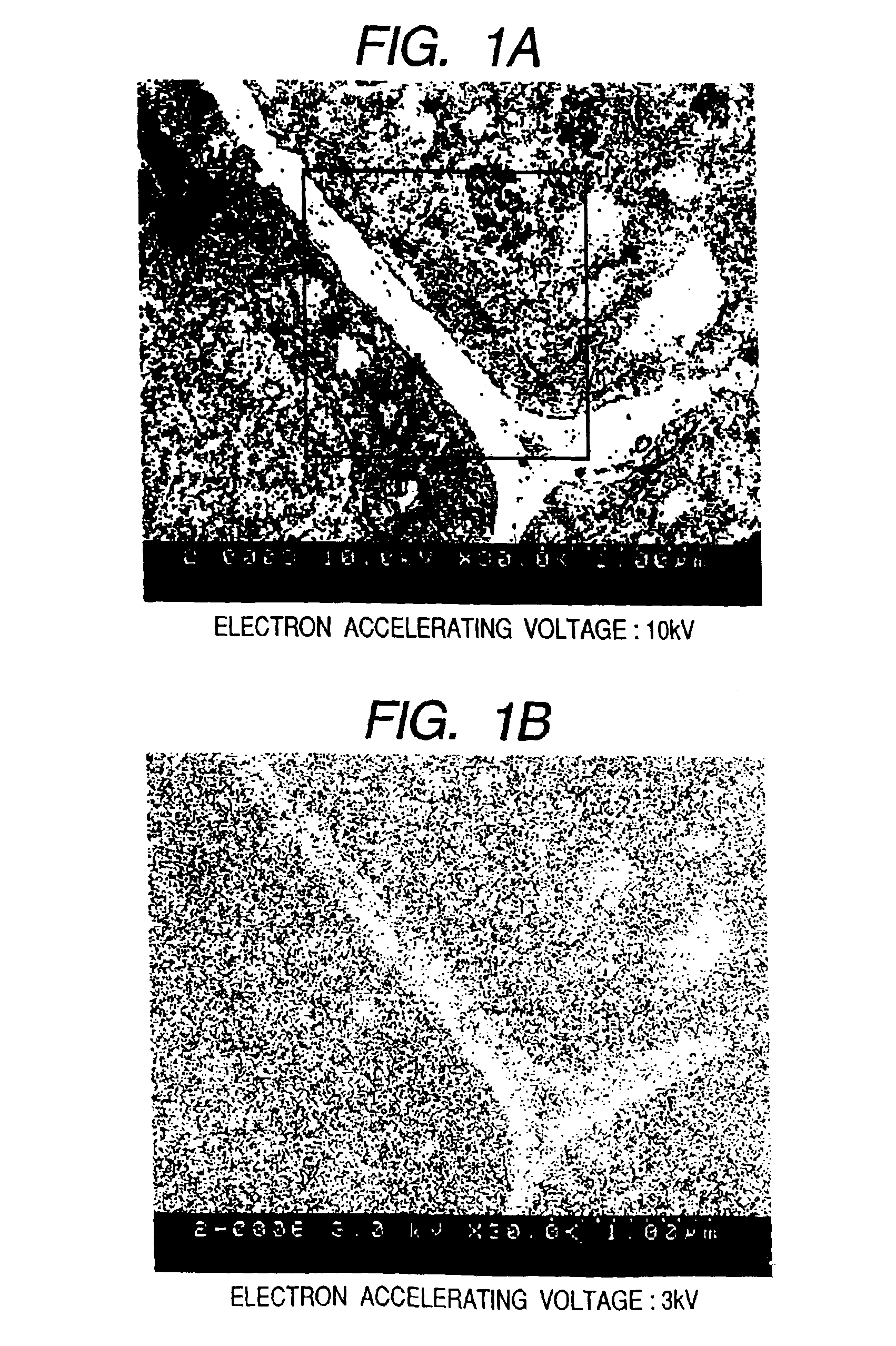
FIG. 1 shows scanning transmission electron microscope images (STEM images) observed using a bio electron microscope and an observation method according to the present invention. A specimen is a stained section specimen of Arabidopsis (plant) and has a specimen thickness of 100 nm. In FIG. 1(a), the specimen is observed by an incident electron beam having an optimum accelerating voltage of 10 kV, and in FIG. 1(b), the specimen is observed by an incident electron beam having a critical electron accelerating voltage possible to transmit a specimen of 3 kV (The definitions of the critical electron accelerating voltage possible to transmit a specimen and the optimum accelerating voltage are described later.). The former can obtain image qualities such as a resolution and contrast which are by no means inferior to the prior art bio transmission electron microscope (TEM) of a 100 kV accelerating voltage class. In other words, ...


PUM


Abstract

A bio electron microscope and an observation method which can observe a bio specimen by low damage and high contrast to perform high-accuracy image analysis, and conduct high-throughput specimen preparation. 1) A specimen is observed at an accelerating voltage 1.2 to 4.2 times a critical electron accelerating voltage possible to transmit a specimen obtained under predetermined conditions. 2) An electron energy filter of small and simplified construction is provided between the specimen and an electron detector for imaging by the electron beam in a specified energy region of the electron beams transmitting the specimen. 3) Similarity between an observed image such as virus or protein in the specimen and a reference image such as known virus or protein is subjected to quantitative analysis by image processing. 4) A preparation protocol of the bio specimen is made into a chip using an MEMS technique, which is then mounted on a specimen stage part of an electron microscope to conduct specimen introduction, preparation and transfer onto a specimen holder.

Description

BACKGROUND OF THE INVENTION1. Field of the InventionThe present invention relates to an electron microscope which can irradiate an electron beam onto a specimen and detects an electron transmitting the specimen or a secondary electron and a reflected electron emitted from the surface of the specimen to obtain a magnified image. More specifically, the present invention relates to a bio electron microscope.2. Description of the Related ArtTo observe, in particular, a bio specimen using an electron microscope, there are fine structure analysis of tissues, structure analysis of protein, and examination of virus. In recent years, various diseases including bovine spongiform encephalopathy (BSE), communicable disease such as HIV and HIC, food poisoning due to O157, and carbon fungus terrorism have been increased. Needs for high-reliability analysis and examination by a highly-magnified image observation using an electron microscope are on the increase. When noted virus and protein are fin...

Claims


Application Information

Patent Timeline
IPC IPC(8): H01J37/26H01J37/22G01N23/04G01N1/28G01N23/225G01N33/483G01N37/00H01J37/20H01J37/28
CPCH01J37/22H01J37/26H01J2237/2813H01J2237/2809H01J2237/05
Inventor KAKIBAYASHI, HIROSHIHOSOKI, SHIGEYUKITAKAGI, YUJIMIYAKE, RYONAKAMURA, KUNIYASUSATO, MITSUGUKOBAYASHI, HIROYUKI
Owner HITACHI HIGH-TECH CORP
Why Eureka
Try Eureka