Printing plate material

Active Publication Date: 2005-07-05
KONICA MINOLTA INC
View PDF7 Cites 60 Cited by
  • Summary
  • Abstract
  • Description
  • Claims
  • Application Information

AI Technical Summary

Benefits of technology

[0055]Generally in the printing plate material comprising the component layer described above, the component layer at portions to be removed should be a layer with a low strength to the extent that it can be removed with water or with a dampening water and/or printing ink on a printing press, while the component layer at portions not to be removed should be a layer with a high strength to the extent that it can provide a printing durability capable of printing several hundred thousand copies. However, it is difficult to make a great difference between portions to be removed and not to be removed. Accordingly, a convexoconcave structure of a substrate surface at portions to be removed has a great influence on the removability. This tendency may be greatly marked when an attempt is made to increase printing durability.
[0056]The thickness of the component layer is preferably smaller, since it is preferred that the component layer has a surface with a convexoconcave structure employing that of the substrate surface, when it is employed as non-image portions during printing. The total thickness of the component layer is preferably not more than 5 g/m2, and more preferably from 0.1 to 3 g/m2.
[0057]When the component layer is employed as image portions during printing, it is preferred that the substrate surface itself is employed as non-image portions. Accordingly, the configuration

Problems solved by technology

Therefore, when a printing plate material having a broad layer thickness distribution is exposed, exposure may be excessive in some portions of the material but insufficient in other portions of the material, which may result in lowering of latitude of exposure.
In a printing plate material comprising an grained aluminum plate, which is imagewise exposed and developed to form an image, developability is affected by the convexoconcave structure of the grained aluminum plate surface, and particularly, a printing plate material comprising an aluminum plate having deep pits on the surface and a component layer provided thereon is difficult to develop on account of the component layer deeply incorporated in the pits.
In contrast, a p

Method used


Image

  • Printing plate material
  • Printing plate material
  • Printing plate material

Examples


Example

Example 1

>

(Preparation of Substrate 1)

[0131]A 0.24 mm thick aluminum plate (1050, H16) was immersed in an aqueous 1% by weight sodium hydroxide solution at 50° C. to give an aluminum dissolution amount of 2 g / m2, washed with water, immersed in an aqueous 0.1% by weight hydrochloric acid solution at 25° C. for 30 seconds to neutralize, and then washed with water.

[0132]Subsequently, the aluminum plate was subjected to an electrolytic surface-roughening treatment in an electrolytic solution containing 10 g / liter of hydrochloric acid and 0.5 g / liter of aluminum at a peak current density of 50 A / dm2 employing an alternating current with a sine waveform, in which the distance between the plate surface and the electrode was 10 mm. The electrolytic surface-roughening treatment was divided into 12 treatments, in which the quantity of electricity used in one treatment (at a positive polarity) was 40 C / dm2, and the total quantity of electricity used (at a positive polarity) was 480 C / dm2. Stan...

Example

Example 2

>

(Preparation of Oleophilic Layer Coating Solution)

[0155]The following materials are mixed in order to obtain an oleophilic layer coating solution.

[0156]Colloidal silica Snowtex-XS (solid content of11.25 parts by weight20% by weight, produced byNissan Kagaku Co., Ltd.)Acryl emulsion AE986A (solid content of 35.5% 4.23 parts by weightby weight, produced by JSR Co., Ltd.)Infrared absorbing dye ADS830WS (produced by 1.25 parts by weightAmerican Dye Source Co., Ltd.)Pure water83.27 parts by weight

[0157]The solid content of the oleophilic layer coating solution was 5.0% by weight.

(Preparation of Hydrophilic Layer Coating Solution)

[0158]The following materials are mixed in order to obtain an hydrophilic layer coating solution.

[0159]Organosilica IPA-ST (solid content of 30% by22.67 parts by weightweight, produced by Nissan Kagaku Co., Ltd.)Polyacrylic acid Julimer AC-10H (solid content 4.00 parts by weightof 20% by weight, produced byNippon Junyaku Co., Ltd.)Aminopropyltriethoxysi...

Example

Example 3

>

(Preparation of Heat Melting Layer 1 Coating Solution)

[0173]The following materials are mixed in order, and a heat melting layer 1 coating solution was obtained.

[0174]Carnauba wax emulsion A118 (solid content of14.00 parts by weight40% by weight, produced byGifu Shellac Co., Ltd.)Trehalose Treha mp. 97° C., produced 7.00 parts by weightby Hayashibara Shoji Co., Ltd.)Infrared absorbing dye ADS830WS (produced 0.70 parts by weightby American Dye Source Co., Ltd.)Pure water 78.3 parts by weight

[0175]The solid content of the heat melting layer 1 coating solution was 7.0% by weight.

(Preparation of Heat Melting Layer 2 Coating Solution)

[0176]The following materials are mixed in order, and a heat melting layer 2 coating solution was obtained.

[0177]PMMA Emulsion Epostar MX-030W (solid56.00 parts by weightcontent of 10% by weight, produced byNippon Shokubai Co., Ltd.)Polyacrylic acid Julimer AC-10S (solid content 1.75 parts by weightof 40% by weight, produced byNippon Junyaku Co., L...


PUM

PropertyMeasurementUnit
Lengthaaaaaaaaaa
Volumeaaaaaaaaaa
Volumeaaaaaaaaaa

Abstract

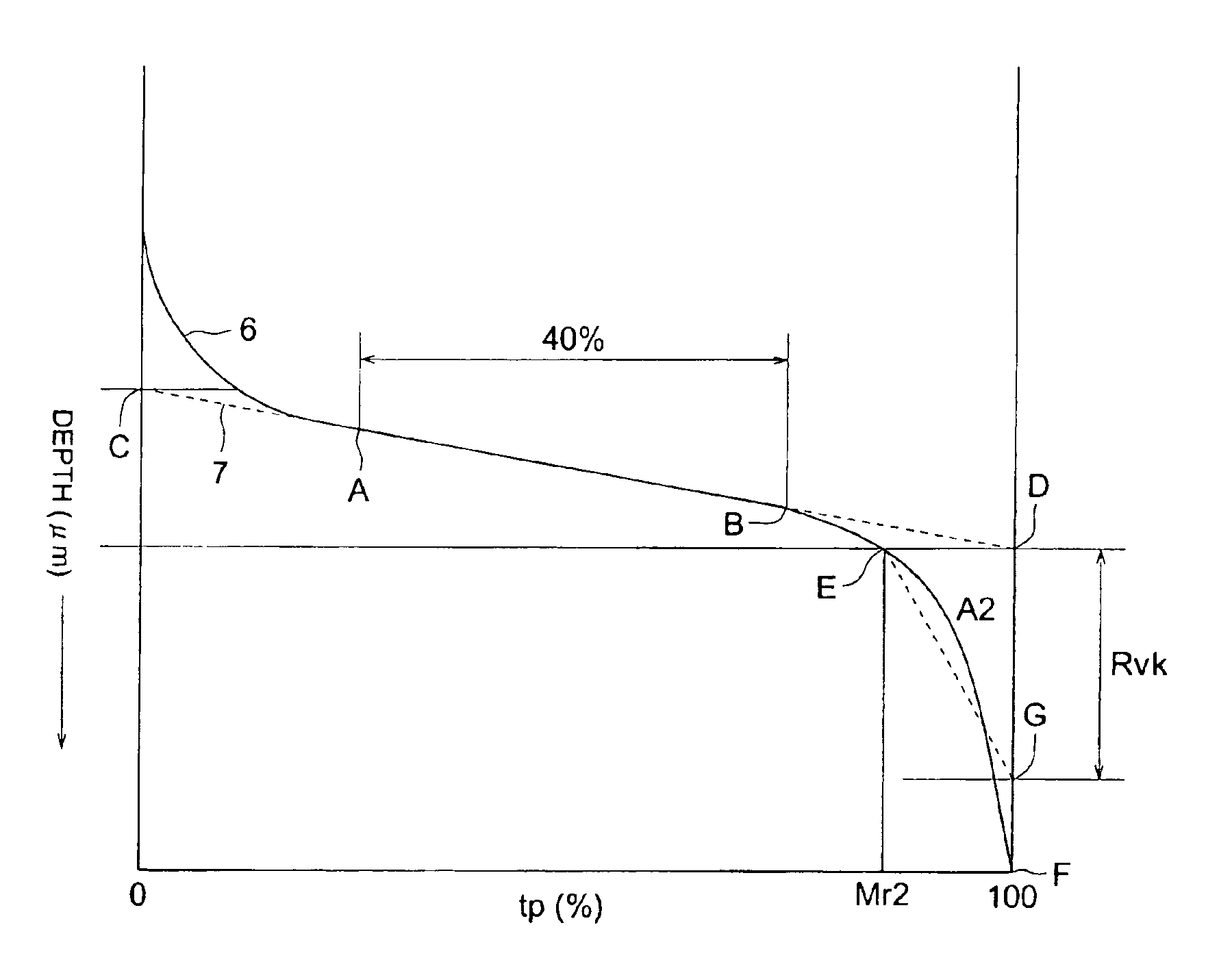
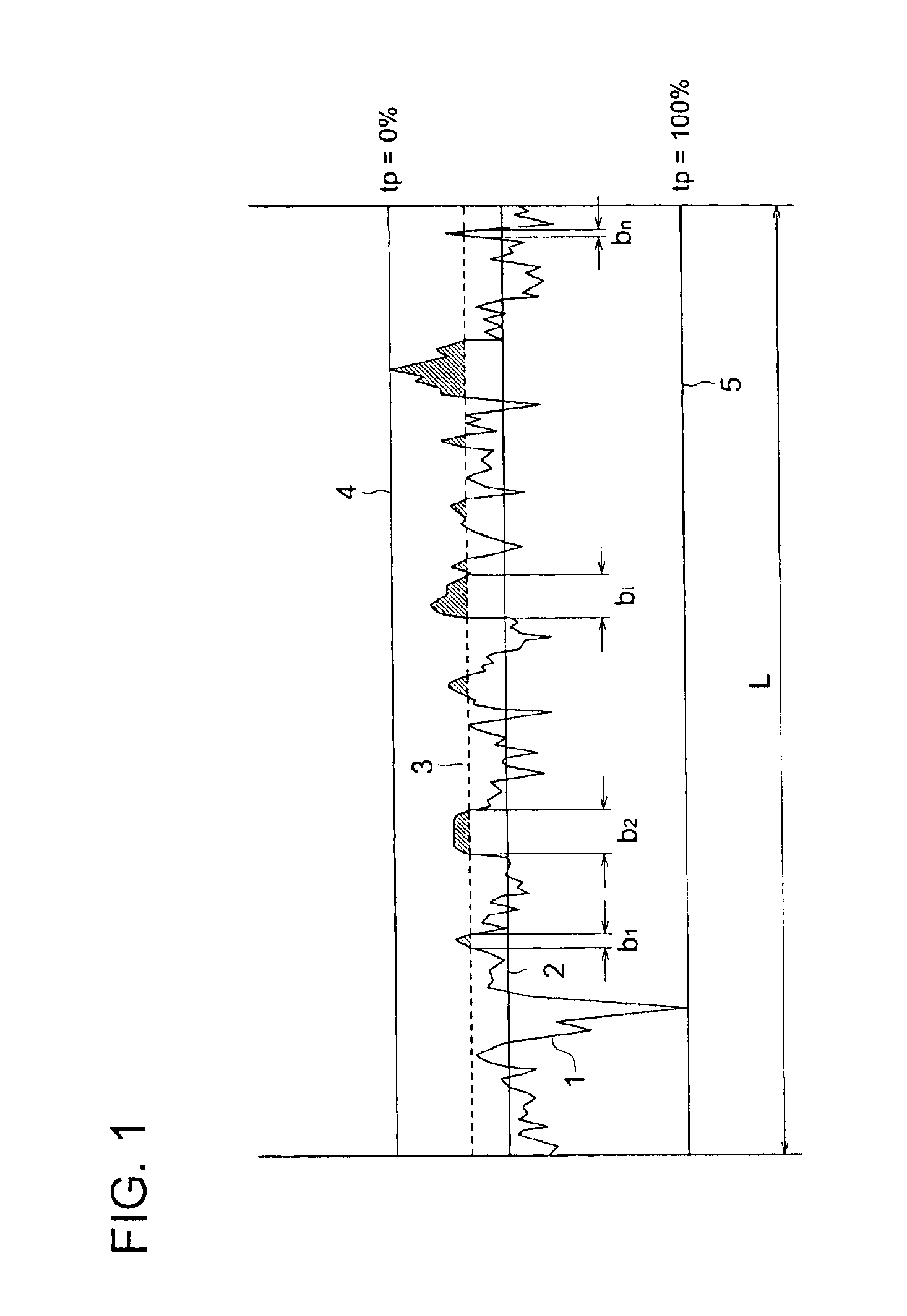
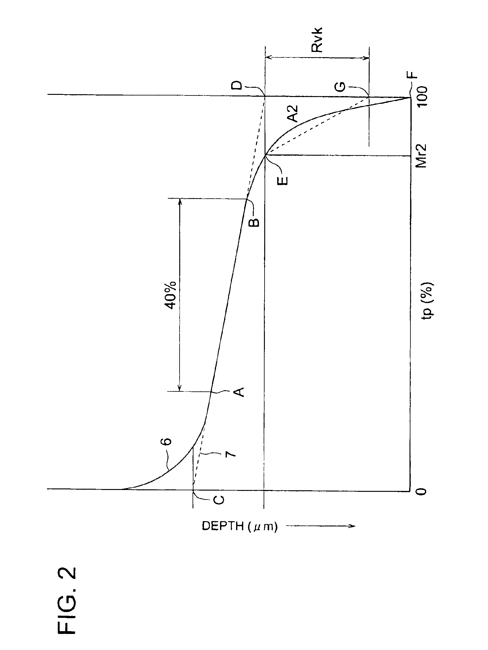
Disclosed is a printing plate material comprising a substrate and a component layer provided thereon, the substrate having a center line average surface roughness Ra of from 0.2 to 1.0 μm, and an oil-retention volume A2 of from 1 to 10, wherein the center line average surface roughness Ra is obtained from three dimension surface roughness measurement according to JIS-B-0601, and wherein an image is capable of being recorded on the component layer by imagewise exposure of infrared laser.

Description

FIELD OF THE INVENTION[0001]The present invention relates to a printing plate material, and particularly to a printing plate material capable of forming an image by a computer to plate (CTP) system.BACKGROUND OF THE INVENTION[0002]The printing plate material for CTP, which is inexpensive, can be easily handled, and has a printing ability comparable with that of a PS plate, is required accompanied with the digitization of printing data. Recently, a versatile thermal processless printing plate material has been noticed which can be applied to a printing press employing a direct imaging (DI) process without development by a special developing agent, and treated in the same manner as in PS plates.[0003]In a printing plate material comprising a metal substrate, particularly a grained aluminum substrate, and provided thereon, a component layer comprising a functional layer on which an image is recorded by imagewise exposure of infrared laser, sensitivity for image formation varies due to ...

Claims


Application Information

Patent Timeline
IPC IPC(8): B41N1/08B41N1/00B41C1/10B41N3/03B41N1/14G03F7/00G03F7/004
CPCB41N1/083B41C1/1008B41N3/034B41C2210/02B41C2210/04B41C2210/08B41C2210/20B41C2210/22B41C2210/24
Inventor MORI, TAKAHIRO
Owner KONICA MINOLTA INC
Why Eureka
Try Eureka