
Compositions and methods for thermosetting molecules in organic compositions

a composition and organic technology, applied in the field of dielectric constant reduction, can solve the problems of limiting the choice of available materials, affecting the quality of thermosetting molecules, and difficult to achieve the effects of reducing the density of crosslinked structures, increasing the length of arms, and increasing the void volum

Inactive Publication Date: 2006-05-23
HONEYWELL INT INC
View PDF3 Cites 2 Cited by
  • Summary
  • Abstract
  • Description
  • Claims
  • Application Information

AI Technical Summary

Benefits of technology

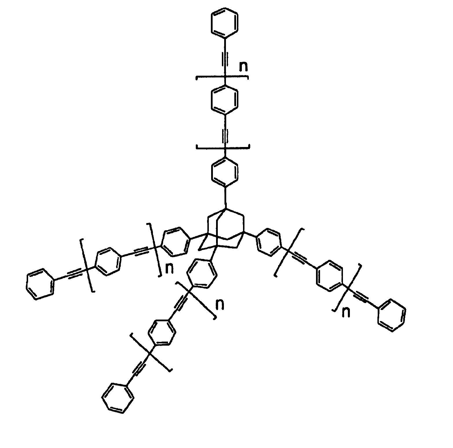
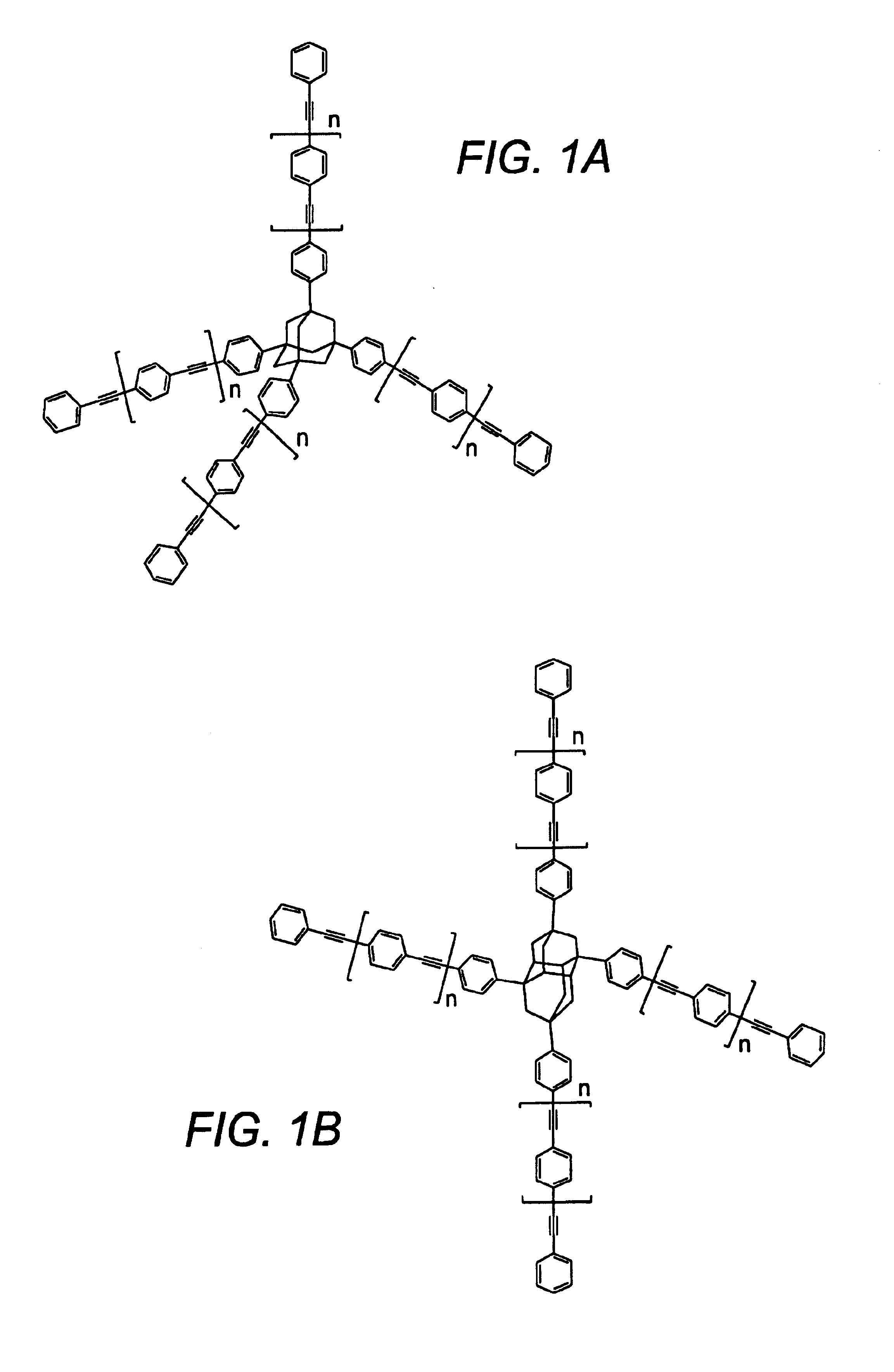
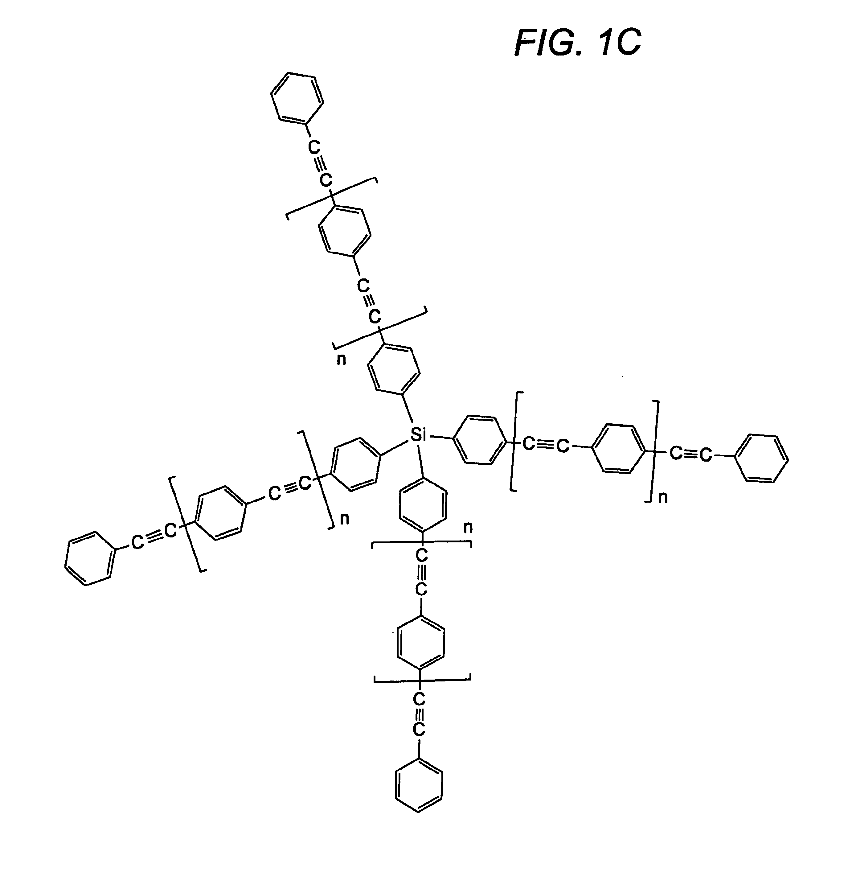
[0012]While it is generally contemplated that the thermosetting monomer is incorporated in a backbone of a polymer, other positions including the termini and side chains are also appropriate. Preferred polymers include poly(arylene ethers) and polymers comprising, or consisting of contemplated thermosetting monomers. It is especially contemplated that by increasing the length of the arms of the thermosetting monomers, the monomers will define an increased void volume between the monomers after crosslinking, thereby decreasing the density of the crosslinked structure and decreasing the dielectric constant of the polymer.

Problems solved by technology

However, while there is typically only poor control over pore size and pore distribution in the physical blending approach, the chemical grating approach frequently poses significant challenges in the synthesis of the polymers and prepolymers and inclusion of various reactive groups (e.g., to enable crosslinking, addition of thermolabile groups, etc.) into the polymers and prepolymers.
Moreover, the chemical nature of both the thermolabile portion and thermostable matrix generally limits processing temperatures to relatively narrow windows which must distinguish the crosslinking (cure) temperature, thermolysis temperature and glass transition temperature, thereby significantly limiting the choice of available materials.
However, the distribution of the glass spheres is typically difficult to control, and with increasing concentration of the glass spheres, the dielectric material loses flexibility and other desirable physico-chemical properties.
Furthermore, glass spheres are generally larger than 20 nm, and are therefore not suitable for nanoporous materials where pores smaller than 2 nm are desired.
Although the pores obtained in this manner are generally very uniform in size, homogeneous distribution of the void carriers still remains problematic.
Moreover, both Rostoker's and Kamezaki's methods require addition or admixture of the void carriers to a polymeric material, thereby adding essential processing steps and cost in the fabrication of nanoporous materials.
Although various methods are known in the art to introduce nanosized voids into low dielectric constant material, all, or almost all of them have disadvantages.

Method used


Image

  • Compositions and methods for thermosetting molecules in organic compositions
  • Compositions and methods for thermosetting molecules in organic compositions
  • Compositions and methods for thermosetting molecules in organic compositions

Examples


example 1

[0040]

Adamantane is brominated to TBA following a procedure as previously described in J. Org. Chem. 45, 5405-5408 (1980), by Sollot, G. P. and Gilbert, E. E.

TBA was reacted with bromobenzene to yield tetrakis(3 / 4-bromophenyl)adamantane (TBPA) as described in Macromolecules, 27, 7015-7022 (1990) by Reichert, V. R. and Mathias L. J. The reaction resulted in the formation of various byproducts. HPLC-MS analysis showed that the yield of the desired TBPA was approximately 50%, accompanied by 40% of the tribrominated tetraphenyl adamantane and about 10 % of the dibrominated tetraphenyladamantane. Unexpectedly, however, when the product mixture was subjected to fresh reagent and catalyst (bromobenzene and AlCl3, 1 min at 20° C.), TBPA was obtained in yields of approximately 90%.

TBPA was reacted with phenylacetylene to yield the final product tetrakis(tolanyl)adamantane following a general reaction protocol for a palladium-catalyzed Heck ethynylation.

example 2

[0041]

[0042]In a 500-mL 3-neck round-bottom flask, equipped with an addition funnel and a nitrogen gas inlet, 4-iodobromobenzene (25.01 g, 88.37 mmoL), triethylamine (300 mL), bis(triphenylphosphine)-paladium[II] chloride (0.82 g) and copper[I] iodide (0.54 g) were added. Then, a solution of phenylacetylene (9.025 g, 88.37 mmoL) in triethylamine (50 mL) was added slowly, and the temperature of the solution was kept under 35 C under stirring. The mixture was stirred for another 4 hours after addition was completed. The solvent was evaporated on the rotary evaporator and the residue was added to 200 mL of water. The product was extracted with dichloromethane (2×150 mL). The organic layers were combined and the solvents were removed by rotary evaporator. The residue was washed with 80 mL hexanes and filtered TLC and HPLC showed a pure product (yield, 19.5 g, 86%). Additional purification was performed by short silica column chromatography (Eluent is 1:2 mixture of toluene and hexanes)....


PUM

PropertyMeasurementUnit
Dielectric constantaaaaaaaaaa

Abstract

In a method of producing a low dielectric constant polymer, a thermosetting monomer is provided, wherein the thermosetting monomer has a cage compound or aryl core structure, and a plurality of arms that are covalently bound to the cage compound or core structure. In a subsequent step, the thermosetting monomer is incorporated into a polymer to form the low dielectric constant polymer, wherein the incorporation into the polymer comprises a chemical reaction of a triple bond that is located in at least one of the arms. Contemplated cage compounds and core structures include adamantane, diamantane, silicon, a phenyl group and a sexiphenylene group, while preferred arms include an arlyene, a branched arylene, and an arylene ether. The thermosetting monomers may advantageously be employed to produce low-k dielectric material in electronic devices, and the dielectric constant of the polymer can be controlled by varying the overall length of the arms.

Description

[0001]This application is a divisional of allowed application Ser. No. 09 / 618,945, filed Jul. 19, 2000 now U.S. Pat. No. 6,469,123.FIELD OF THE INVENTION[0002]The field of the invention is reduction of dielectric constants.BACKGROUND OF THE INVENTION[0003]As interconnectivity in integrated circuits increases and the size of functional elements decreases, the dielectric constant of insulator materials embedding the metallic conductor lines in integrated circuits becomes an increasingly important factor influencing the performance of the integrated circuit. Insulator materials having low dielectric constants (i.e., below 3.0) are especially desirable, because they typically allow faster signal propagation, reduce capacitive effects and cross talk between conductor lines, and lower voltages to drive integrated circuits.[0004]Since air has a dielectric constant of about 1.0, a major goal is to reduce the dielectric constant of insulator materials down towards a theoretical limit of 1, a...

Claims


Application Information

Patent Timeline
IPC IPC(8): C08G63/78C08G61/02C08G61/12C08G65/40
CPCC08G61/02C08G65/40C08G61/12C08G2650/60
Inventor LAU, KREISLER S.LIU, FENG QUANKOROLEV, BORIS A.BROUK, EMMAZHEREBIN, RUSLANNALEWAJEK, DAVID
Owner HONEYWELL INT INC
Learn More