
Three-dimensional braided covered stent

a three-dimensional, covered stent technology, applied in the field of body implantable devices, can solve the problems of limiting the types of materials that can be interbraided into the device, difficult to provide a device, etc., to achieve the effect of enhancing radial self-expansion, facilitating the confinement of the latticework, and reducing manufacturing costs

Inactive Publication Date: 2006-05-30
LIFESHIELD SCI
View PDF55 Cites 101 Cited by
  • Summary
  • Abstract
  • Description
  • Claims
  • Application Information

AI Technical Summary

Benefits of technology

[0019]A salient feature of the process is that the structural strands are selectively shaped, i.e. given their predetermined second nominal shapes, prior to the interbraiding step. Consequently, process conditions for selective shaping have virtually no impact on the textile strands. This is particularly beneficial when the structural strands are metallic, e.g. formed of Elgiloy or another cobalt-based alloy, certain stainless steels, or a recovery metal such as Nitinol nickel-titanium alloy. These metals provide the desired strength and resiliency, yet when thermally shaped require temperatures far above the melting points typical of the multifilament yarns suitable for the textile strands. Certain polymers suitable for the structural strands likewise are advantageously shaped at temperatures unsuitably high for the textile strands. In either event, thermally setting or shaping the structural strands prior to interbraiding prevents this kind of damage to the textile strands.
[0020]In accordance with the present invention, structural strands may be selectively shaped by cold working as well. Certain resilient and ductile metals are particularly well suited to cold working. Examples of highly preferred alloys in this regard are discussed in U.S. patent application Ser. No. 08 / 640,253 (now U.S. Pat. No. 5,891,191) entitled “Cobalt-Chromium-Molybdenum Alloy Stent and Stent-Graft,” assigned to the assignee of this application and filed concurrently herewith. A primary advantage of cold working is the ability to incorporate the cold-working step and the braiding step into a continuous operation. In particular, each structural strand on its way to a braiding station can be wrapped about a shaping pulley under sufficient tension to achieve the desired plastic deformation. Continuous shaping and braiding substantially reduce manufacturing cost.
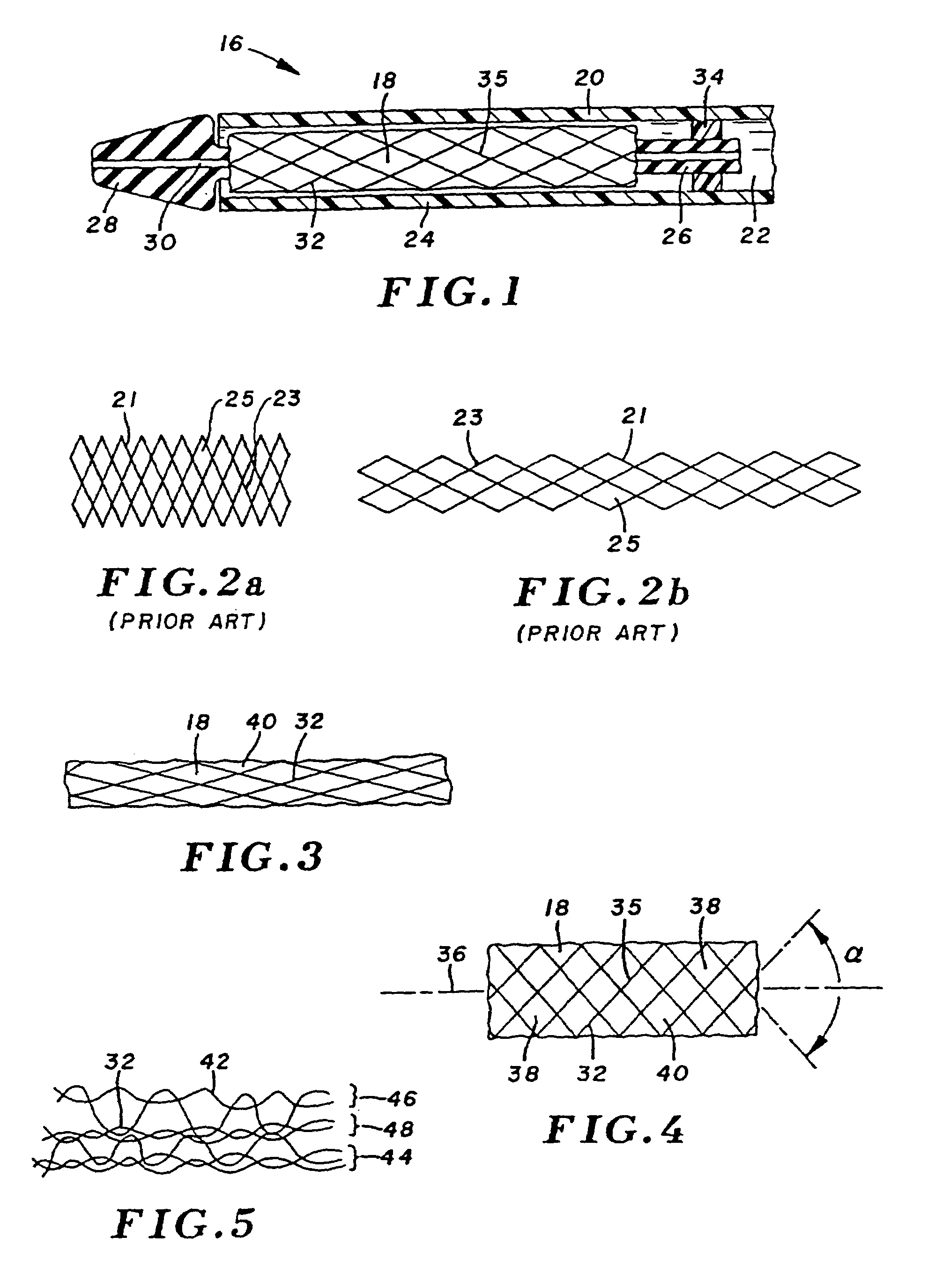
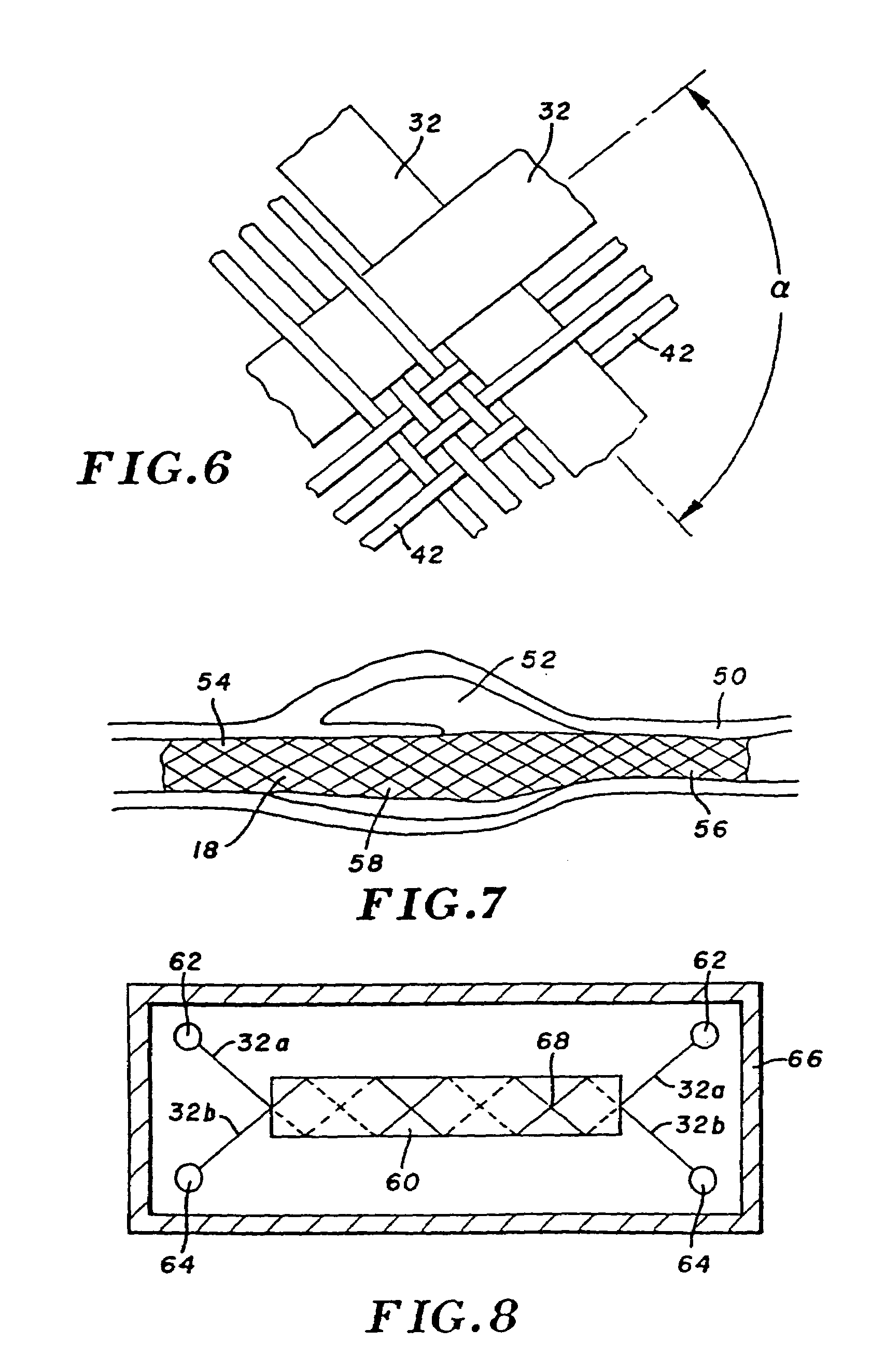
[0021]The structural strands can be formed into a variety of shapes, most preferably helical. The helices can be wound in a single direction so that the interstices are helical. More frequently, the structural strands are wound as two sets of helices running in opposite directions, to form a latticework in which the interstices are rhombic. The oppositely directed helices can be interbraided, or can overlie one another, being interbraided only with the textile strands. The interbraided structure can incorporate further strands, for example of radiopaque material. The structure can incorporate one or more elastomeric strands running axially of the structure and fused to the structure along at least part of its axial length, thus to enhance radial self-expansion.
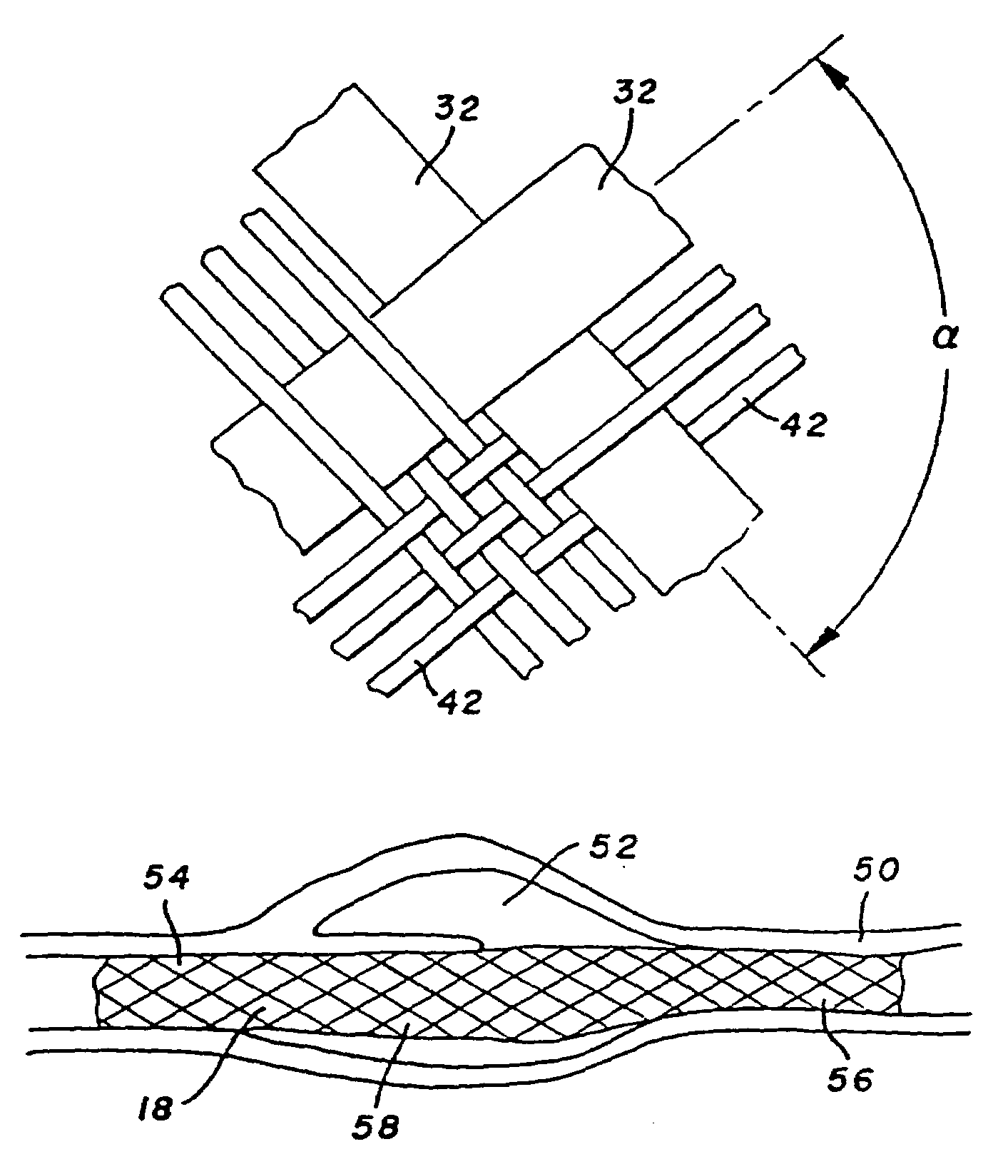
[0022]As compared to structures formed by conventional two-dimensional braiding techniques, three-dimensionally braided structures tend to have a more even distribution of forces among the structural strands. Three-dimensional braiding enables a controlled structuring of tubular prosthesis, for example to provide radial gradients in permeability, porosity, strength or other structural properties. A three-dimensionally braided structure with three or more discrete layers facilitates confining a latticework of structural strands to a medial layer, providing a textile cover on both sides of the latticework.
[0023]The process can be augmented with several steps that enhance the utility of the prosthesis, such as coating the structural strands, the textile strands, or both. A heat setting step may be performed after braiding, when the textile strands are formed of a yarn amenable to heat setting. An adhesive can be applied to the ends of the integrated structure after braiding, to reduce unraveling.
[0027]Thus in accordance with the present invention, a three-dimensionally braided structure incorporating structural and textile strands is manufactured according to a process that enables a controlled shaping of the structural strands without adversely affecting the textile strands. The result is an intraluminal device with the favorable qualities of an open weave stent and of a tightly woven graft. The structural strands are shaped either thermally or by plastic deformation, before they are brought together with the textile strands for interbraiding. The interbraiding step involves all strands simultaneously, interweaving a compliant textile sheeting among the structural strands as the structural strands are formed into a latticework that defines the shape of the prosthesis. As a result, the textile sheeting is supported by the latticework and tends to conform to the shape of the latticework. The textile sheeting exhibits low permeability and high compliance, preventing leakage of blood or other fluids, yet readily accommodating radial contractions and expansions of the structural latticework.

Problems solved by technology

Those of skill in the art have generally encountered difficulty in providing a device that simultaneously accommodates the competing needs of low permeability, and strength and flexibility for considerable radial compression and expansion.
Otherwise, either an oversized graft is compressed between the stent and body tissue with undesirable folds or gathering of the graft material, or an undersized graft prevents the stent from expanding sufficiently to anchor the device.
Accordingly, all strands and filaments must be compatible with the heat set conditions (primarily the high temperature), limiting the types of materials that can be interbraided into the device.

Method used


Image

  • Three-dimensional braided covered stent
  • Three-dimensional braided covered stent
  • Three-dimensional braided covered stent

Examples


example 1

[0078]The bobbins of the carrier assembly (FIG. 13) are loaded with two hundred and twenty-four textile strands of polyester, each being 70 denier and composed of forty-seven filaments. More particularly, all of the bobbins in sets 80, 82, 86 and 88 are loaded with the polyester yarn. These textile strands also are loaded onto thirty-two of the bobbins in central set 84. Of the remaining sixteen bobbins, eight bobbins installed on carriers in the clockwise direction, and eight bobbins installed in the counterclockwise direction, are loaded with sixteen structural strands. The structural strands are arranged symmetrically, in that in each direction, every third bobbin is loaded with one of the structural strands. Each structural strand is an Elgiloy wire having a diameter of 0.0047 inches (0.12 mm). The strands are braided onto an 8 mm diameter round mandrel, with the braider operated to determine a braid angle of 110°. The braid is formed to an adequate length, then removed from the...

example 2

[0080]As in Example 1, the textile strands are 70 denier polyester yarns composed of forty-seven filaments. One hundred and sixty-eight of the polyester yarn textile strands are loaded (FIG. 14) as follows: onto all the bobbins of outer set 88, its adjacent set 86, and set 82. Twenty-four bobbins of central set 84 also are loaded with the polyester yarn. The remaining twenty-four bobbins of the central set are loaded with Elgiloy wire, again having a diameter of 0.0047 inches. Twelve of these bobbins are installed in the clockwise direction, and twelve in the counterclockwise direction, with every second bobbin being wound with a structural strand. All bobbins of inner set 80 are loaded with a 70 denier collagen fiber. The strands are braided onto an 8 mm diameter round mandrel, with the braider operated to determine a braid angle of 110°.

[0081]The result is a tubular, three-dimensionally braided structure of the polyester yarn and metal monofilaments, with an inner layer of fibers ...

example 3

[0082]As in Example 1, all the bobbins in sets 80, 82, 86 and 88 are loaded with the textile strands, each being a 70 denier polyester yarn composed of forty-seven filaments. In set 84 corresponding to a central layer of the finished structure, twenty-four of the carrier bobbins likewise are loaded with the polyester multifilament yarn. The remaining twenty-four bobbins are loaded with a 0.0047 inch diameter Elgiloy wire. In this case, all twenty-four bobbins installed in the clockwise direction are loaded with the Elgiloy wire. The strands are braided onto an 8 mm diameter round mandrel, with the braider operated to determine a braid angle of 110°. This arrangement is not illustrated.

[0083]The result is a tubular three-dimensionally braided structure of the polyester yarn and metal monofilaments. The wire latticework consists of spirals wound in the clockwise direction.


PUM

PropertyMeasurementUnit
braid angleaaaaaaaaaa
weight percentaaaaaaaaaa

Abstract

A prosthesis for transluminal implantation consists of a flexible tubular three-dimensionally braided structure of metal or polymeric monofilaments, and polymeric multifilament yarns. The prosthesis can be elastically deformed to reduce its diameter through axial elongation. The monofilaments and multifilament yarns are arranged in axially spaced apart helices, concentric on a common central axis of the prosthesis. The monofilaments are selectively shaped before their interbraiding with the multifilament yarns, either by an age-hardening or other heat-setting stage, or a cold-working stage that controllably plastically deforms the strands. The shaped structural strands cooperate to impart to the prosthesis its nominal shape and resilience. The textile strands cooperate to provide one or more layers of sheeting that reduce permeability and thereby enhance the utility of the prosthesis as a vascular graft. An alternative embodiment prosthesis includes elastically and plastically deformable structural strands, selectively plastically deformed by cold working, then three-dimensionally braided to form the prosthesis.

Description

[0001]This is a divisional of application Ser. No. 09 / 761,512 (now U.S. Pat. No. 6,592,617), filed Jan. 16, 2001 as a divisional of application Ser. No. 09 / 198,558 (now U.S. Pat. No. 6,342,068), filed Nov. 23, 1998 as a continuation of application Ser. No. 08 / 920,542 (now abandoned), filed Aug. 27, 1997 as a divisional of application Ser. No. 08 / 640,091 (now U.S. Pat. No. 5,718,159), filed Apr. 30, 1996.BACKGROUND OF THE INVENTION[0002]The present invention relates to body implantable devices, and more particularly to prostheses including stents and grafts intended for long term or permanent intraluminal fixation.[0003]A variety of patient treatment and diagnostic procedures involve the use of devices inserted into the body of a patient and intraluminally implanted. Among these devices are prostheses as disclosed in U.S. Pat. No. 4,655,771 (Wallsten). These devices are flexible, tubular, braided structures formed of helically wound thread elements. A delivery catheter includes gripp...

Claims


Application Information

Patent Timeline
Patent Type & Authority Patents(United States)
IPC IPC(8): A61F2/06A61F2/00A61F2/02A61F2/90D04C1/06
CPCA61F2/90D04C1/06A61F2/06A61F2/0077Y10T428/2922A61F2/07A61F2/95A61F2002/072A61F2210/0004A61F2240/001A61F2250/0067A61F2250/0098A61F2210/0076A61F2220/0008A61F2220/0016A61F2220/0075D10B2509/06D04C3/40D04C3/48D04C3/36D10B2401/061
Inventor THOMPSON, PAUL J.
Owner LIFESHIELD SCI
Learn More