Axial-flow blood pump with magnetically suspended, radially and axially stabilized impeller

a technology of axial flow and impeller, which is applied in the direction of piston pumps, positive displacement liquid engines, prosthesis, etc., to achieve the effects of reducing coagulation, long operation life, and reducing siz

Inactive Publication Date: 2006-07-04
UNIV OF VIRGINIA ALUMNI PATENTS FOUND +1
View PDF67 Cites 107 Cited by
  • Summary
  • Abstract
  • Description
  • Claims
  • Application Information

AI Technical Summary

Benefits of technology

[0029]It has been recognized that it would be advantageous to develop a reliable ventricular assist device for permanent implantation in humans. In addition, it has been recognized that it would be advantageous to develop a blood pump to reduce coagulation, avoid secondary flow paths, and provide an open, one-pass blood path. In addition, it has been recognized that it would be advantageous to develop a blood pump with a reduced size, long operational life and lower power consumption requirements. In addition, it has been recognized that it would be advantageous to develop a blood pump with a hybrid permanent magnet and electromagnetic set with permanent magnets to manage greater forces (axial or thrust) and an electromagnet to manage lesser forces (radial). In addition, it has been recognized that it would be advantageous to develop a blood pump with optimum configuration permanent and electromagnetic bearings to enable the best blood pump flow performance. In addition, it has been recognized that it would be advantageous to develop a blood pump with proper start up direction of rotation. In addition, it has been recognized that it would be advantageous to develop a blood pump with control methods that consume less power and produce less heat to facilitate an active magnetic bearing component.

Problems solved by technology

A reduction in cardiac output leads to poor perfusion, fluid accumulation, and activation of salt-water retention mechanisms.
Due to a limited number of donor hearts available each year (˜2,500), CHF patients often require MCS as a bridge-to-transplantation and many such patients may fail to survive awaiting a donor organ.
Despite the tremendous need for an effective ventricular assist pump, prior MCS devices have not been entirely successful due to several limiting factors.
Particular concerns and design limitations of current blood pump designs include: 1) component durability and lifetime; 2) blood clotting or thrombosis due to flow stasis within the pump in secondary flow areas, wash ports, and recirculation regions, and platelet activation in regions of high shear stress; 3) blood trauma or hemolysis that may occur when blood contacts mechanical bearings or foreign surfaces, and when blood is subjected to higher than normal shear conditions due to rotating components; 4) percutaneous leads which are needed for the motor and bearing control systems and other support lines; 5) pump geometry (size, shape, and weight) for ease of implantation, patient mobility, avoidance of graft tears; 6) high cost of the pump; and 7) high power demand that requires a large power supply.
These pulsatile pumps, however, have proven to be very complicated mechanically, are relatively large and have relatively short mechanical lifetimes. An alternative design using a rotary pump leads to the use of the mechanical heart as a ventricular assist device which does not require explantation of the native heart.
Studies have shown several problems with poor rotary blood flow path design in both axial flow and centrifugal flow blood pumps including those with magnetic suspension.
One of these problems is stagnation resulting in thrombosis or clotting.
As the thrombosis builds up, a section or large clot may break off and embolize in the blood stream.
If the clot occludes a blood vessel that enters the brain or other sensitive area, very serious conditions may develop, such as profound organ dysfunction, such as seizure or severe brain damage.
Another problem is hemolysis, where blood is exposed to high shear stresses in the rotary pump, usually near the impeller blades which move at relatively high speed, and which may cause direct or delayed damage to the circulating blood.
As the impeller applies forces to the blood, regions of turbulence and / or jet formation, can occur in poorly designed devices.
There are many disadvantages to this type of pump.
The percutaneous supply and delivery of the lubricant purge fluid degrades the patient's quality of life and provides a high potential for infection.
Seals for the external lubricant are notoriously susceptible to wear and to fluid attack which may result in leakage and the patient having a subsequent seizure.
Also, an additional pump is needed for delivery of the lubricant to the bearing, and if it fails the lubricated bearing freezes.
Finally, the mechanical bearings have a finite wear life, usually of a few years, and need to be replaced due to the bearing wear.
Also, there have been reported cases of thromboembolism in some patients.
It is believed that the large thrust disk obstructs the blood path and creates a tortuous blood path which is far from straight through the pump.
Laser sensors cannot be used because they cannot “look through” the opaque blood.
Capacitance probes require an electrical path between the stator and rotor which is generally not feasible with blood pumps.
There are several problems associated with the use of an eddy current or inductive sensor types in the gap in between the stator and rotor of an implantable miniature blood pump.
One problem with these types of sensors is the possible contamination of the blood stream if the soft iron or other non-biocompatible sensor faces are exposed to the blood.
Other problems are space constraints required for the sensor, and the energy budget required for such sensors.
There is no brush wear so the expected life of such pumps is very long.
One issue with such pumps is assuring that the motor will start in the necessary direction for the impeller to pump.
The proper start up direction of rotation can be an important issue.
Active magnetic bearings can be composed of soft iron magnetic materials which have a significant limitation in that they are subject to magnetic saturation at a certain level, typically at about 1 Tesla.
The use of the bias linearization method, as just described, has a major disadvantage that it has relatively high power consumption in the coils, and generates large heating in the coils which may overheat the active magnetic bearing component of the rotary blood pump.
Further, there are limitations on this type of bias linearization which prevent the full utilization of the magnetic force capacity of the active magnetic bearing.
Another issue with regard to proper centered operation of the rotary pump impeller is the unbalance in the rotor.
Rotating devices are subject to mechanical unbalance as it is difficult to manufacture a perfectly balanced rotor.
In addition, during operation within the patient over a long period of time, additional changes in unbalance may take place due to rotor component shifting, rotor rubbing, blood or blood products adhesion to the impeller surfaces, and other factors.
Higher bias current levels result in higher power consumption and higher heating.
It has been found, however, that centrifugal flow pumps are not easily implantable in either animals or humans because the inflow and outflow cannulas are located at 90 degrees relative to each other and in separate planes.
In addition, such centrifugal pumps require convoluted secondary blood flow paths as part of the design.

Method used


Image

  • Axial-flow blood pump with magnetically suspended, radially and axially stabilized impeller
  • Axial-flow blood pump with magnetically suspended, radially and axially stabilized impeller
  • Axial-flow blood pump with magnetically suspended, radially and axially stabilized impeller

Examples


Embodiment Construction

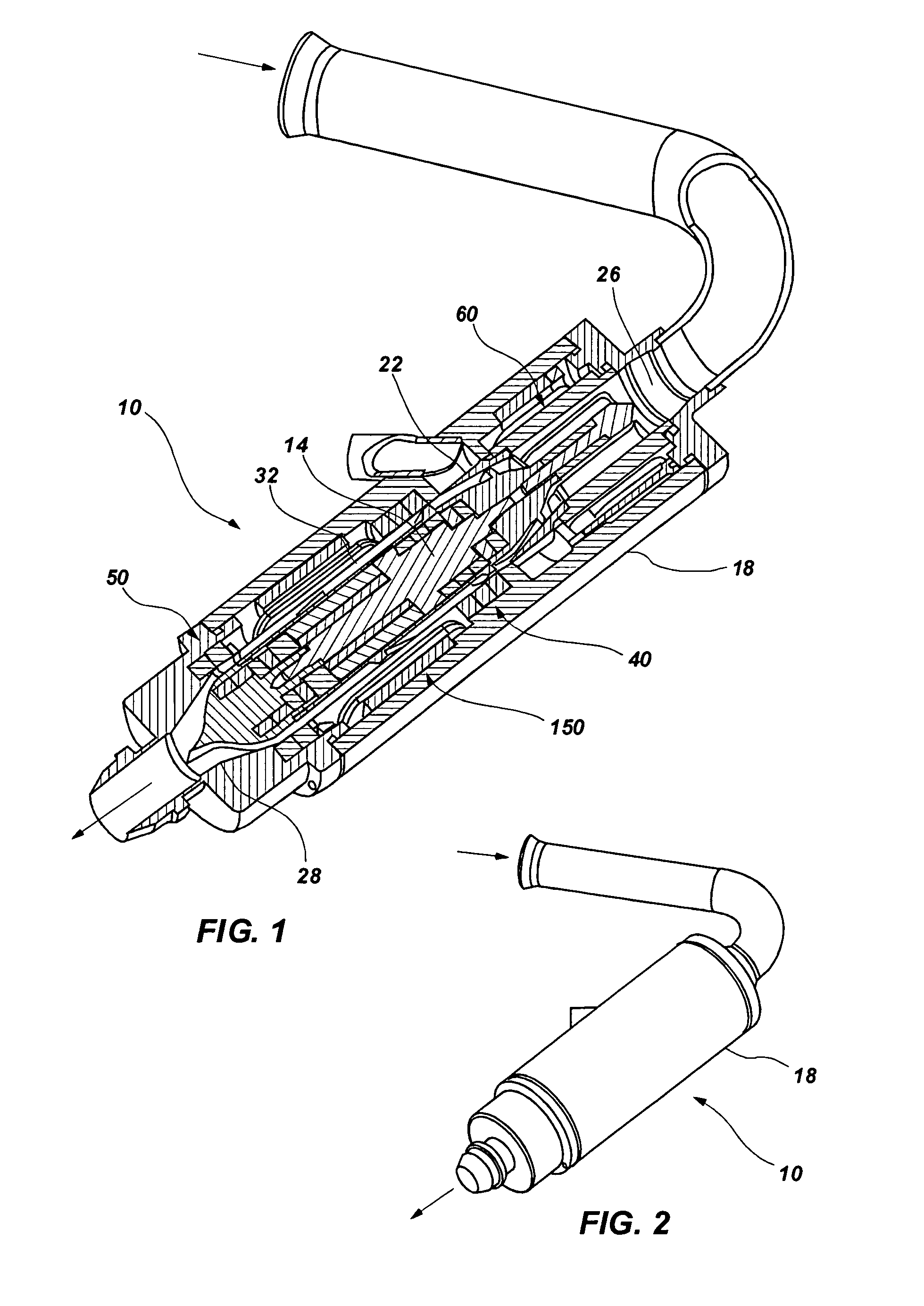
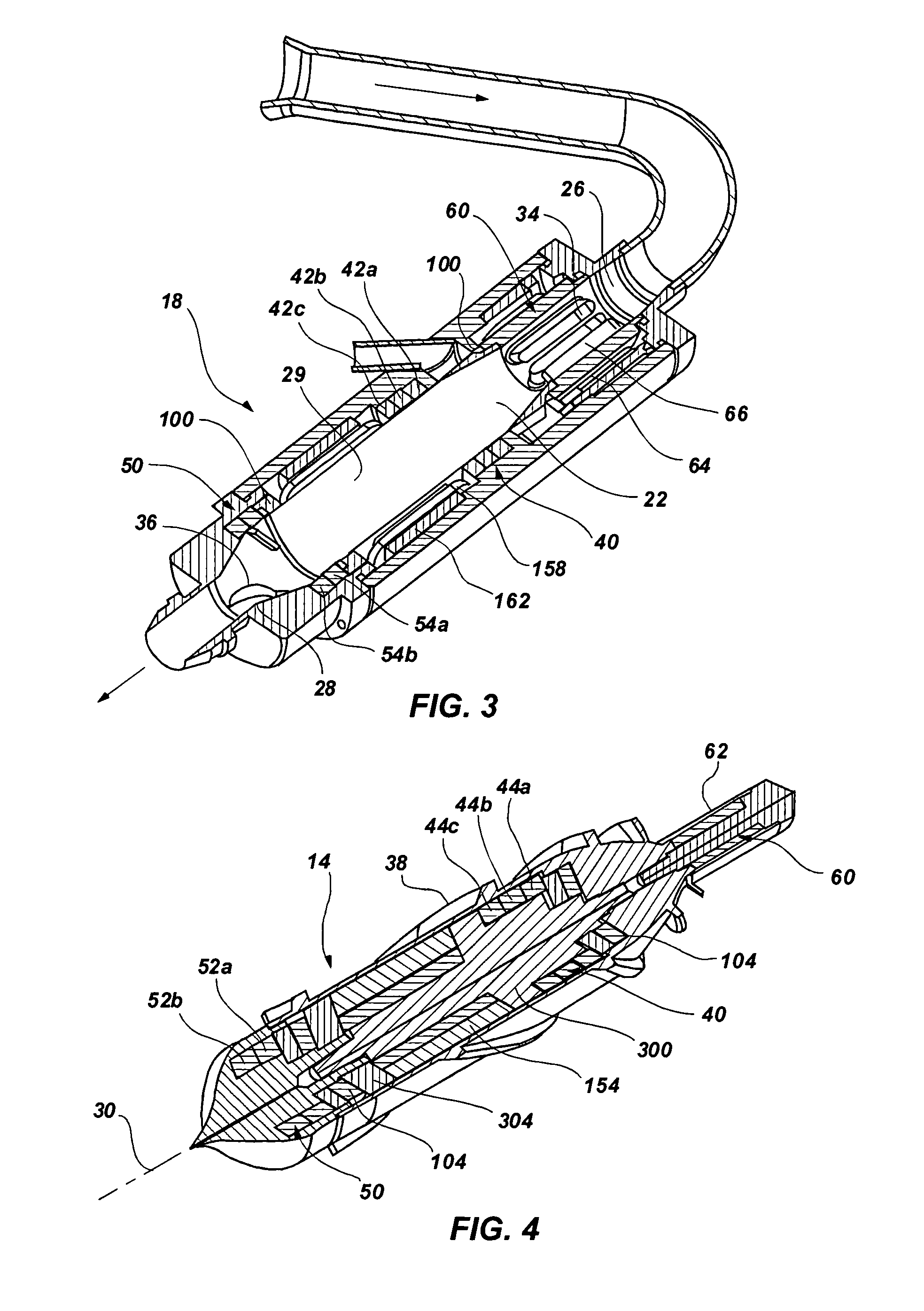
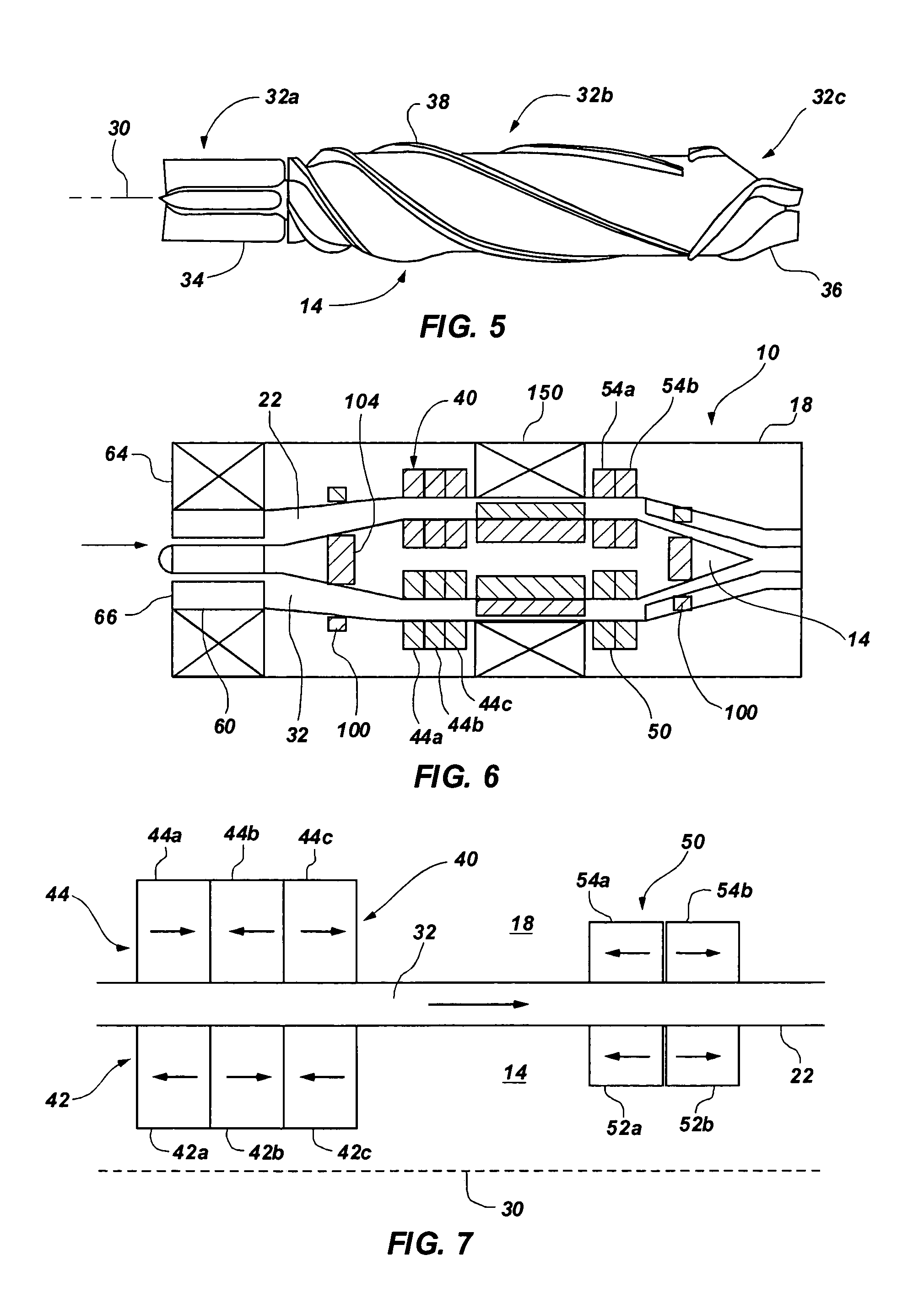
[0055]As illustrated in FIGS. 1–8 and 10a–b, an exemplary embodiment of a compact, axial flow, rotary blood pump, indicated generally at 10, is shown with a magnetic suspension and rotating system. Such a pump can be utilized as a ventricular assist device (VAD) for those who suffer from congestive heart failure (CHF). The pump 10 advantageously includes a magnetic suspension and rotating system that reduces size, has long operational life and lowers power consumption requirements. In addition, the pump 10 advantageously includes an unobstructed one-pass blood design without a secondary blood path for any magnetic suspension clearances, as opposed to previous magnetic suspension systems requiring both primary and secondary blood paths. Thus, the pump 10 advantageously minimizes the incidence of flow stasis leading to thrombosis, as well as hemolysis by avoiding secondary flow paths

[0056]The magnetic suspension uses 1) one permanent magnet, passive, axially centering, thrust bearing;...


PUM


Abstract

A blood pump has an impeller rotatably disposed and magnetically suspended within a cavity of a stator by a plurality of magnetic bearings including an axial bearing to support the impeller axially in the cavity. The axial bearing includes adjacent impeller magnets and adjacent stator magnets with axially aligned polarities and reverse polarities with respect to adjacent magnets. A motor includes impeller magnets on the impeller and coils and poles associated with the stator. Radial permanent magnet and electromagnetic bearings are also included. The magnetic bearings and the motor have stator magnets or coils and poles disposed radially across the fluid passage from corresponding impeller magnets to define an annular gap positioned radially between the impeller and the stator, and positioned radially between all of the plurality of magnetic bearings, creating a straight through blood path without secondary flow paths.

Description

PRIORITY CLAIM[0001]Benefit is claimed of U.S. Provisional Patent Application Ser. No. 60 / 506,023 filed on Sep. 25, 2003, which is herein incorporated by reference.[0002]This application is related to U.S. patent application Ser. No. 10 / 950,176, filed Sep. 24, 2004, which is herein incorporated by reference.GOVERNMENT LICENSE RIGHTS[0003]The U.S. Government has a paid-up license in this invention and the right in limited circumstances to require that the patent owner to license others on reasonable terms as provided for by the terms of Grant No. NIH HL64378 awarded by the National Institutes of Health (NIH).BACKGROUND[0004]1. Field of the Invention[0005]The present invention relates generally to axial-flow blood pumps suitable for permanent implantation in humans as a chronic ventricular assist device.[0006]2. Related Art[0007]An effective and reliable axial-flow blood pump can provide mechanical circulatory support (MCS) to thousands of patients each year. An estimated 4.8 million ...

Claims


Application Information

Patent Timeline
Patent Type & Authority Patents(United States)
IPC IPC(8): A61M1/10F04B17/00A61M60/178A61M60/237A61M60/422A61M60/82F04B35/04
CPCF16C32/0448F16C2316/18F16C32/0461A61M60/82A61M60/422A61M60/237A61M60/178
Inventor OLSEN, DON B.ALLAIRE, PAUL E.WOOD, HOUSTON G.KIPP, RONALDJIANG, WEILIN, ZONGLILI, GUOXIN
Owner UNIV OF VIRGINIA ALUMNI PATENTS FOUND
Why Eureka
Try Eureka