Partially-open fired heater cycle providing high thermal efficiencies and ultra-low emissions

Inactive Publication Date: 2006-07-11
AES DEV CO
View PDF40 Cites 132 Cited by
  • Summary
  • Abstract
  • Description
  • Claims
  • Application Information

AI Technical Summary

Benefits of technology

[0057]In a heater cycle system example FIG. 2‘alternate configuration’ for process heating applications where a heater unit is required to heat more than one process fluid flow stream to a high temperature that is within an approximate 50° F. example temperature of the given highly superheated HTF, two or more parallel-positioned heat exchanger sections can be provided. Each heat exchanger section receives a controlled flow portion of combined and then manifold-divided high superheated HTF mass flow emanating from one or more burner assemblies contained within a heater unit to satisfy each heat exchanger section's heat duty service. The HTF mass flow directed in one-pass flow through each parallel-po

Problems solved by technology

The long resident times, in which high temperature extended length combustion was maintained within the earlier heaters, resulted in extremely high flue gas emissions.
This reduction in fugitive emissions is achieved however with an accompanying significant added operating expensive for the production of de-mineralized boiler grade water required for steam or liquid water injection to prevent fouling of heat exchanger coils within a given type of heater.
Due to the high temperatures and varied conventional burner designs' flame speeds and non-uniform temperatures throughout all portions of the multi-staged combustion zones, it is not possible to accurately predict what series of altered chemical reactions occur when water vapor and/or carbon dioxide are introduced into a given burner's currently developed individual fuel combustion zones.
However, preheating air tends to have the effect of increasing a burner's primary combustion zone temperature thereby increasing the burner susceptibility to increased NO.sub.x generation.
The infrastructure to support wide scale and efficient distribution of these chemical

Method used


Image

  • Partially-open fired heater cycle providing high thermal efficiencies and ultra-low emissions
  • Partially-open fired heater cycle providing high thermal efficiencies and ultra-low emissions

Examples


Example

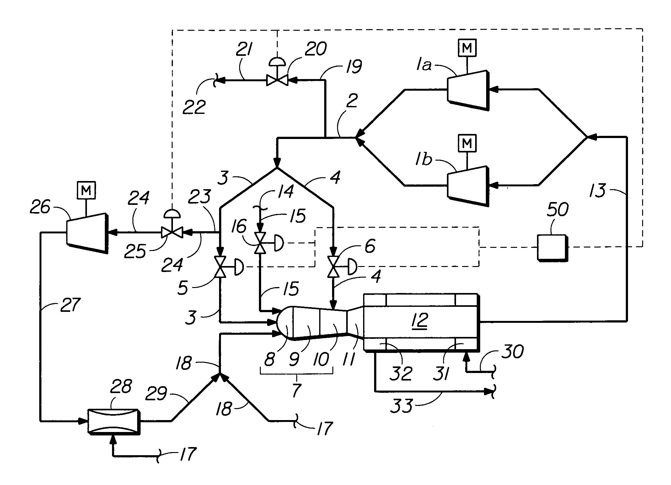
[0072]Referring now more particularly to FIG. 1, the heater cycle system is hereafter described with its ‘base configuration’ comprising common employed cycle components, as well as a ‘alternate configuration’ component means that can be alternately incorporated with the ‘base configuration’ heater cycle system components.

[0073]The invention's cycle ‘base configuration’ re-circulated flue gas stream contained within RFG collection manifold 13 can be supplied to either one blower unit or compressor unit 1a or to two or more blower units or compressor units positioned in parallel (as shown by the FIG. 1 with example of 1a and 1b blower units or compressor units) to re-pressurize and discharge the heater re-circulated flue gas into a single common primary re-pressurized RFG conduit manifold 2. Primary re-pressurized RFG conduit manifold 2 comprises parallel end-branch conduit means 3 and 4. Conduit 3 can contain flow control valve means 5 for the end-connected transfer of the controlle...


PUM


Abstract

A partially open fired heater regenerative cycle wherein the fired industrial type heater cycle's heat transfer fluid replaces the air predominant nitrogen heat transfer fluid employed in a conventional air/fuel combustion heater. The heater cycle's method and apparatus means is susceptible to providing a 95 to 98 percent mass flow reduction of fugitive nitrogen oxide and carbon monoxide mass flow emissions as emitted by current art Low-NO.sub.x art heaters on a rated per million Btu per hour basis, and is further susceptible to developing steady-state heat transfer thermal efficiencies exceeding 124 percent.

Description

BACKGROUND OF THE INVENTION[0001]In the case of conventional forced or induced draft burners employed within heater unit categories such as steam generators, boilers, tube heaters, process furnaces and process heaters, motor-driven fans or blowers provide the means of creating a forced or induced draft of atmospheric air into a heater unit's burner unit assembly.[0002]For complete combustion of varied gaseous or liquid fuels, a 120% to 200% quantity of stoichiometric air was typically employed in earlier conventional heater and burner designs. The long resident times, in which high temperature extended length combustion was maintained within the earlier heaters, resulted in extremely high flue gas emissions. The supply of air is increased above stiochiometric level to both supply an excess of oxygen (hereafter may be referred to as O.sub.2) for completed combustion and for added fluid mass flow heat absorption to lower example air / methane stoichiometric adiabatic combustion flame zo...

Claims


Application Information

Patent Timeline
IPC IPC(8): F23J9/00F02C1/08
CPCF02C1/08
Inventor NEARY, DAVID LLOYD
Owner AES DEV CO
Why Eureka
Try Eureka