

Cleaning compositions containing hydroxylamine derivatives and processes using same for residue removal
a technology of hydroxylamine derivatives and cleaning compositions, which is applied in the direction of detergent compounding agents, washing machines, instruments, etc., can solve the problems of long shelf life, long activity of compositions, and difficult to completely remove etching residues without damaging the substrate,
- Summary
- Abstract
- Description
- Claims
- Application Information
AI Technical Summary
Benefits of technology
Problems solved by technology
Method used
Image

Examples
example 1
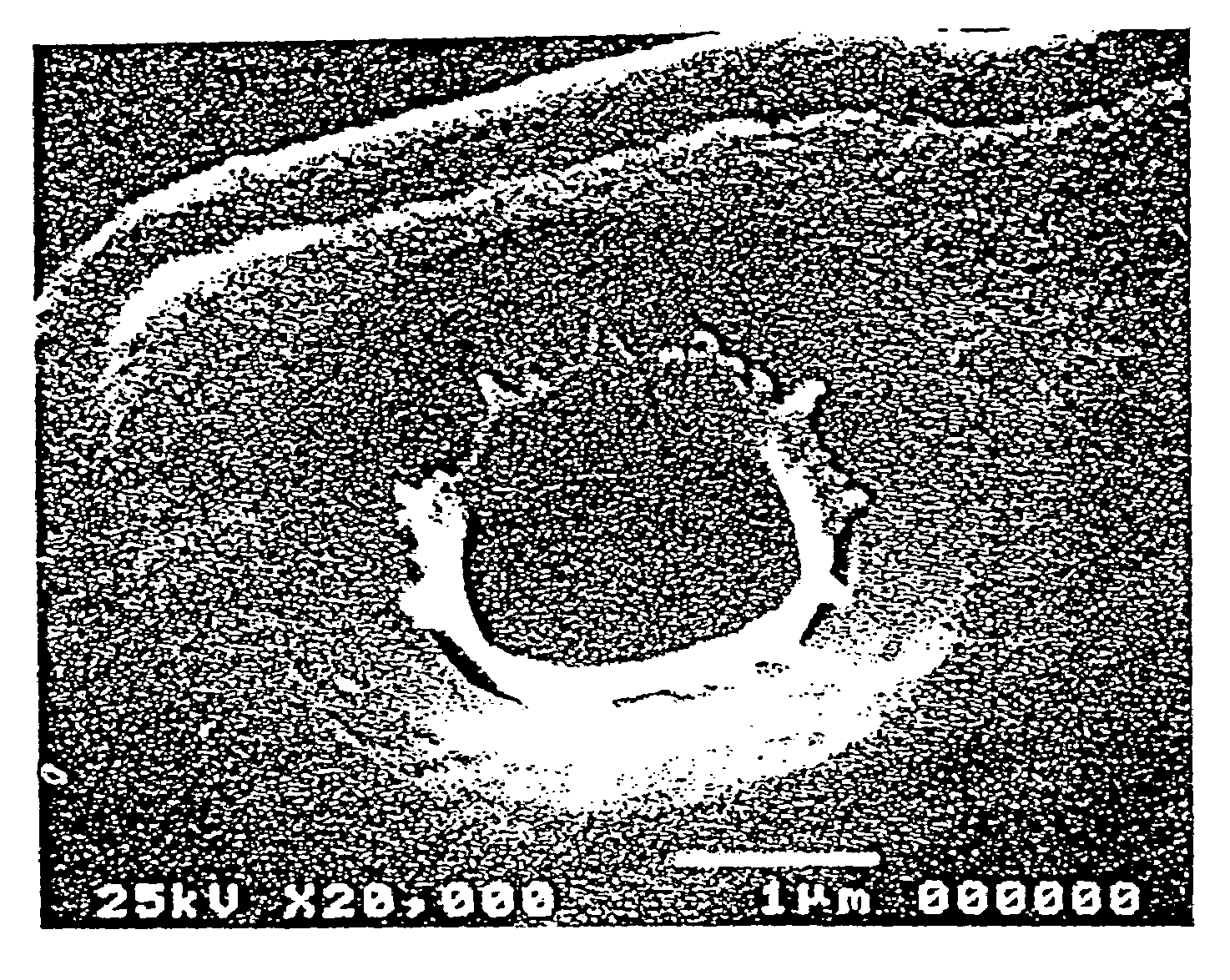
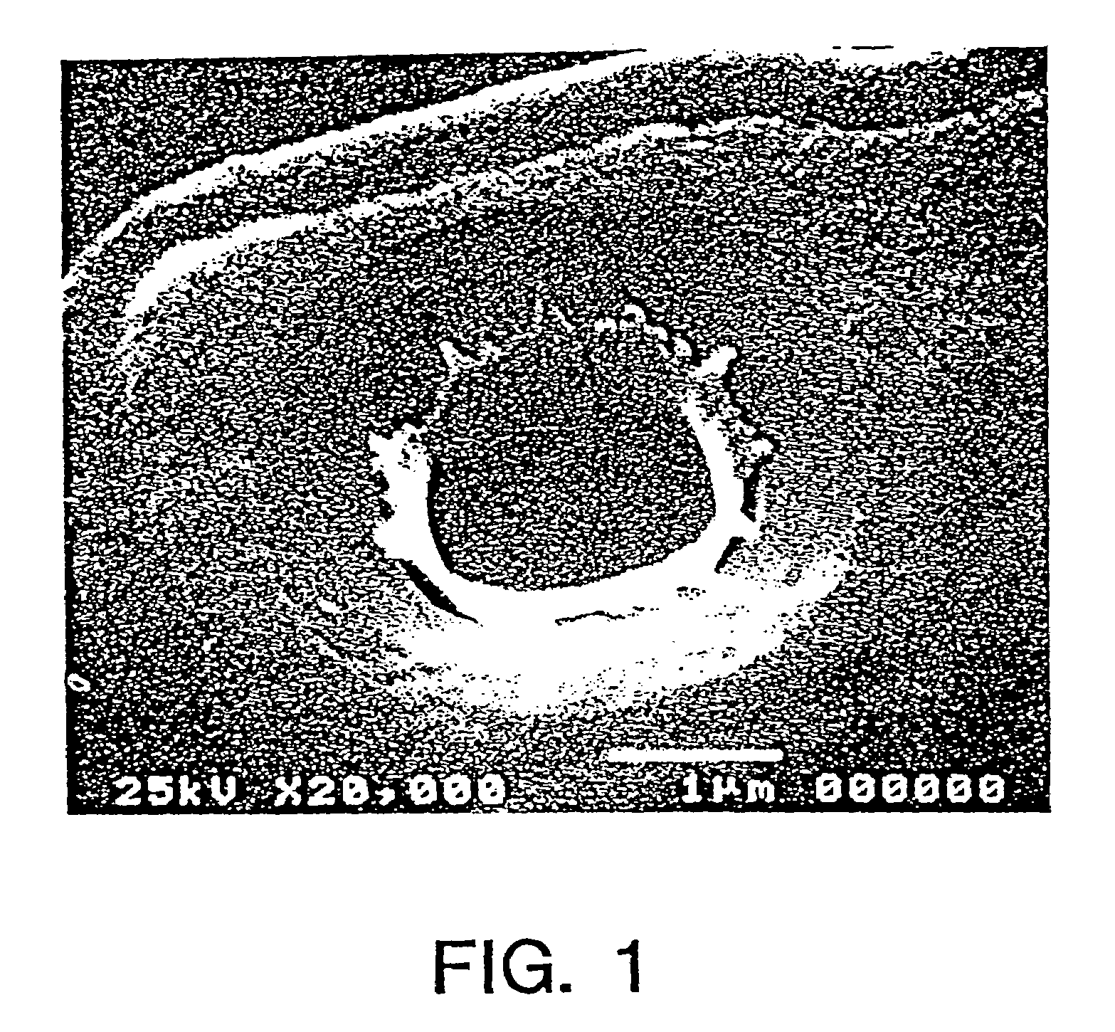
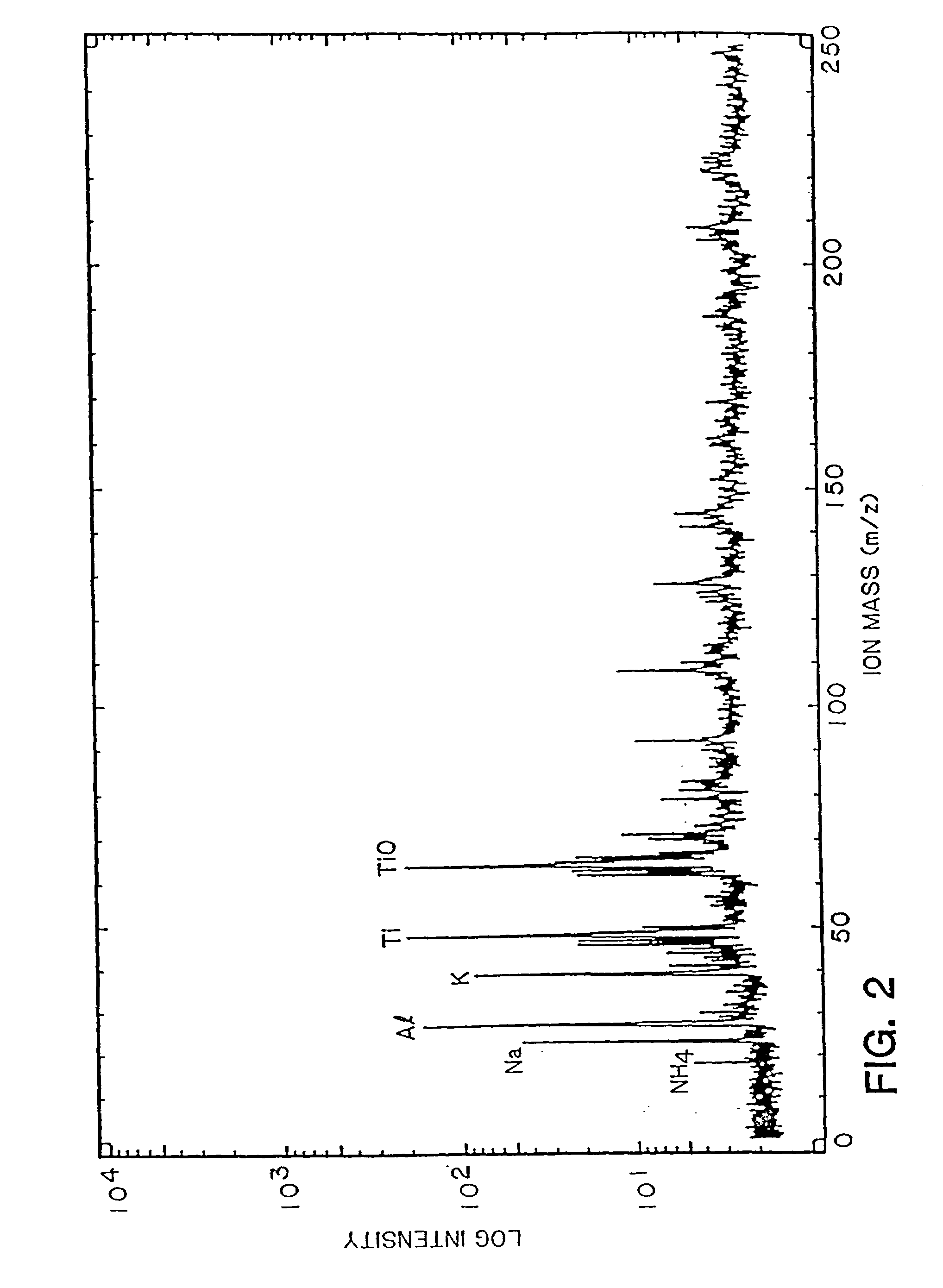
[0178]Example 1 illustrates the problem of residue remaining on a wafer substrate following plasma etching and ashing. FIG. 1 shows etched wafer residue present on an etched substrate following plasma ashing. Specifically, silicon oxide used as a dielectric layer has a pattern etched for a multi-layer interconnect according to a standard plasma etching process. A photoresist which was used as a masking material has already been removed by oxygen plasma ashing. Analysis of the residue present on the etched wafer was analyzed by ion mass spectrometry (LIMA). The results of the analysis are as shown in FIG. 2. The analysis confirms that the residue contains metal oxide and trace amounts of organic material.
example 2
[0179]Example 2 illustrates the effect of the cleaning composition of the present invention on a wafer as determined by C / V testing. C / V shift measurement is a means utilized to determine the effect of a chemical used to clean a wafer. A high voltage shift is mainly caused by mobile ion contamination to the wafer. Such contamination will adversely affect subsequent process steps and may eventually cause failure of the microcircuits.
[0180]The test evaluation compares the C / V shift of different conventional photoresist stripping compositions to the cleaning composition of the present invention. All wafers used were known to be good silicon oxide substrates. All chemicals were heated on a hot plate to the manufacturers' suggested operating temperature using a pyrex beaker. Each of the beakers utilized was new and had not been previously used in any chemical processing. Individual beakers were used for each product. After immersing the silicon oxide wafer in the described composition, t...
example 3
[0183]Example 3 illustrates the results of a comparison test between Composition F of the present invention as described above and the stripping composition described in U.S. Pat. No. 4,403,029 and sold under the name PRS-2000 by J. T. Baker. The results of the comparison test are shown with respect to an opening having the size of 1.2 micron in FIGS. 3A and 3B. Each opening was present on a silicon oxide dielectric layer which was etched using a standard silicon oxide plasma etching process. The photo-resist was removed from the layer following etching by oxygen plasma ashing. The substrate was then processed by immersing the substrate in Composition F as described above for 10 minutes at 65° C. A micrograph from a scanning microscope as shown in FIG. 3A indicates that Composition F removed all the organometallic residue. As shown in FIG. 3B, residue remained on the substrate when an etched wafer prepared under the same process conditions was processed by immersion in PRS-2000 for ...
PUM
| Property | Measurement | Unit |
|---|---|---|
| flash point | aaaaa | aaaaa |
| flash point | aaaaa | aaaaa |
| temperatures | aaaaa | aaaaa |
Abstract
Description
Claims
Application Information