Device and method for melting a substance with the occurrence of a low level of contamination

a technology of contamination and melting device, which is applied in the direction of glass reforming device, glass tempering device, glass pressing device, etc., can solve the problems of reducing the melting temperature of the substance, so as to improve the melting temperature and throughput , the effect of increasing the melting capacity

Inactive Publication Date: 2007-11-20
SCHOTT AG
View PDF19 Cites 13 Cited by
  • Summary
  • Abstract
  • Description
  • Claims
  • Application Information

AI Technical Summary

Benefits of technology

[0026]Therefore, it is an object of the present invention to provide an apparatus and a method, in particular a skull melting apparatus or a skull melting method, for melting a substance, in particular glass or glass-ceramic, which allow an improved homogeneity, an increased melting capacity, an increased throughput and / or a high substance or glass quality to be achieved.

Problems solved by technology

A drawback of such methods is that some of the platinum is released to the melt, and the refractory tank furnaces have only short service lives.
The desired high-purity glass quality cannot be achieved in this case.
Firstly, the maximum melt temperature is limited by the crucible or tank furnace material. Therefore, the melting crucible or melting tank furnace and if appropriate the refining channel and the homogenization tank furnace usually consist of platinum, which has a relatively high melting point and is relatively resistant to corrosion.
Furthermore, the platinum melting crucible or the platinum melting tank furnace, and also the refining channel and the homogenization tank furnace, is attacked and corroded by the glass melt.
In any case, platinum disadvantageously leads to contaminations or impurities in the glass, which have an adverse effect on the optical properties, in particular the transmission, and consequently these conductive-heating methods can only be used to a very restricted extent for high-purity glasses.
Impurities of this nature lead to transmission losses in optical fiber transmission systems of up to 200 to 500 dB / km.
This has proven extremely problematical in particular for the melting of aggressive glasses, e.g. zinc silicate or lanthanum borate glasses, since these glasses cause extensive corrosion to the crucibles or tank furnaces.
However, the complex structure, in particular the high-frequency technology requirements of an inductively heated skull melting device, results in completely new requirements and problems compared to the abovementioned conductive-heating melting apparatuses.
Firstly, the high melting temperature and very high throughtput rates per crucible volume means that many solution approaches for conductive-heating apparatuses cannot readily be transferred to skull melting apparatuses.
Although this is desirable, on the other hand this may under certain circumstances cause the quality of the melt and therefore of the end product to suffer, for example as a result of thermal reduction.
This also leads to a deterioration in the transmission properties of the glass.
Therefore, the melting performance is restricted not only by the high-frequency power emitted by the coil arrangement but also by the melting parameters and crucible geometries.
The result is a convective flow, but the flow rate of this convective flow is slow enough to ensure that raw material cannot or can scarcely descend into the melted glass.
As a result, however, the redox state of the melt is only locally changed and the melt as a whole is not homogenized.

Method used


Image

  • Device and method for melting a substance with the occurrence of a low level of contamination
  • Device and method for melting a substance with the occurrence of a low level of contamination
  • Device and method for melting a substance with the occurrence of a low level of contamination

Examples


first embodiment

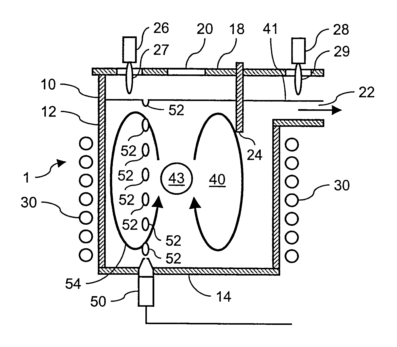
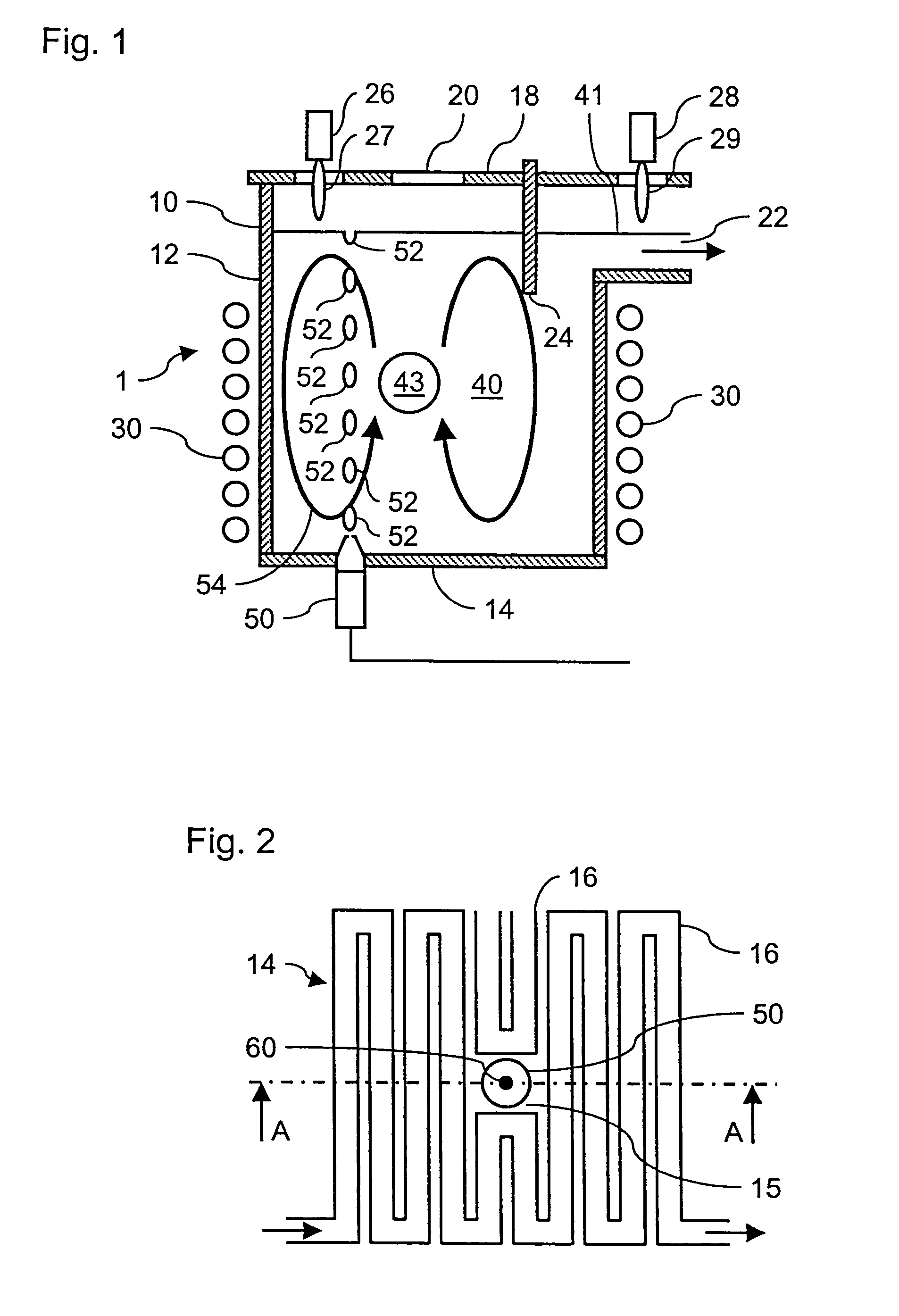
[0058]FIG. 1 shows the apparatus 1 according to the invention for melting glass, having a cooled, e.g. water-cooled, crucible or melting crucible 10. An emitting device for emitting electromagnetic radiation, in the form of a coil arrangement 30, is arranged around the crucible 10. High-frequency power is introduced into a melt 40, for example comprising lead silicate glass, by means of the coil arrangement, so that the melt 40 is heated. A high frequency of approximately 250 kHz to approximately 400 kHz at an emission power of approximately 200 kW to approximately 300 kW or higher is used. The temperature of the melt is in the range from 1200° C. to 2000° C.

[0059]The crucible 10 comprises a water-cooled annular wall section 12 and a water-cooled base 14. The wall section 12 and the base 14 together form the cooled wall of the crucible 10 and each comprise metal tubes 16 which are arranged in meandering form and are spaced apart from one another, as can be seen most clearly from FIG...

second embodiment

[0074]FIG. 7 shows the apparatus 101 according to the invention, with an alternative device 150 for mixing and homogenizing the melt 40. Glass batch which has been formed into pellets, coated pills and / or beads 156 is introduced, via a conveyor belt 154, into the melt 40 through the opening 20. The glass beads 156 comprise an outer boundary region 158 and an inner core region 160. The boundary region 158 substantially comprises glass of the same composition as the melt 40. The core region 160 comprises a substance which releases a gas or gas bubbles 152 in the melt when the boundary region 158 has melted. The substance in the core region 160 may comprise a gas, a liquid, e.g. water, or a solid material, e.g. a salt, which by interacting with the hot melt 40 release the gas bubbles 152.

[0075]The fact that the glass beads 156 sink in a left-hand section 40a of the melt and the fact that the gas bubbles 152 rise up in a right-hand section 40b of the melt 40 result in a substantially an...

third embodiment

[0076]FIG. 8 shows the apparatus 201 according to the invention, in which batch bodies 256 which have been pressed into the form of rods are introduced into the melt 40 by means of a mixing and homogenization device 250. The bodies 256 in rod form are, for example, shaped in the style of propellers and rotate as they sink within the melt 40, with the bodies 256 being melted at the same time, so as to generate flow phenomena in the melt 40.


PUM

PropertyMeasurementUnit
melting temperaturesaaaaaaaaaa
frequencyaaaaaaaaaa

Abstract

The invention relates to an apparatus and a method for low-contamination melting of high-purity, aggressive and/or high-melting glass or glass-ceramic. According to the invention, for this purpose a melt is heated in a crucible or melting skull crucible by means of high-frequency radiation and is mixed or homogenized in the melting crucible. It is preferable for a gas nozzle, from which gas bubbles, e.g. oxygen bubbles (known as O2 bubbling), escape into the melt, to be provided at the base of the crucible. This alone makes it possible to achieve surprising multiple benefits in the melting skull crucible. Firstly, unmelted batch which drops into the melt in solid form, for example from above, is melted down more quickly as a result of more intensive mixing with the liquid fraction of the melt, secondly the temperature distribution in the melt is made more even, thirdly a uniform distribution or mixing of different glass constituents is achieved, and fourthly the redox state of the glass can be adjusted.

Description

BACKGROUND OF THE INVENTION[0001]1. Field of the Invention[0002]The invention relates to an apparatus and a method for the low-contamination melting of a substance in general and in particular for the melting of high-purity, aggressive and / or high-melting glass or glass-ceramic, specifically.[0003]2. Description of Related Art[0004]In traditional melting methods, glass is melted continuously in a platinum crucible or in refractory tank furnaces. A drawback of such methods is that some of the platinum is released to the melt, and the refractory tank furnaces have only short service lives. The desired high-purity glass quality cannot be achieved in this case.[0005]There are also known methods in which glass is melted continuously in melting tank furnaces and removed. To obtain high-quality glass, a refining channel and a homogenization device or tank furnace may follow the melting tank furnace.[0006]In both the above mentioned methods, discontinuous or continuous, the melting crucible...

Claims


Application Information

Patent Timeline
Patent Type & Authority Patents(United States)
IPC IPC(8): C03B5/18C03B5/185C03B5/187C03B5/193C03B5/06C03B1/02C03B3/00C03B5/02C03B5/20C03B5/26C03C3/097C03C4/00
CPCC03B1/02C03B3/00C03B5/021C03B5/18C03B5/187C03B5/193C03B5/265C03C3/097C03C4/0007C03B5/205Y10S65/04C03B2211/70C03B2211/71Y02P40/57
Inventor LEISTER, MICHAELSCHAFER, ERNST-WALTEREICHBERG, LEOPOLDOHMSTEDE, VOLKER
Owner SCHOTT AG
Why Eureka
Try Eureka