
Perovskite-based fuel cell electrode and membrane

a fuel cell and perovskite technology, applied in the field of fuel cell electrodes, can solve the problems of reducing the commercialization affecting the economic benefits of the economy, and reducing the practical value of these fuel cells, so as to reduce the energy and capital cost and reduce the effect of nox emissions

Inactive Publication Date: 2009-03-17
THE UNIV COURT OF THE UNIV OF GLASGOW
View PDF6 Cites 28 Cited by
  • Summary
  • Abstract
  • Description
  • Claims
  • Application Information

AI Technical Summary

Benefits of technology

[0027]SOFCs using or containing an anode of the present invention may be used to oxidise any fuel appropriate for fuel cell use either directly or after at least partial reformation. Such fuels include hydrogen; hydrogen; a hydrocarbon fuel compound such as methane, ethane, propane, or butane; a hydrocarbon based fuel compound such as methanol or ethanol; and a non-hydrocarbon hydride fuel compound such as ammonia, hydrogen sulphide; as well as mixtures of such compounds such as LPG, gasoline, diesel, biogas, biofuel, kerosene, or JP8.

Problems solved by technology

The practical commercial development of these has, though, been held back by numerous practical problems.
Significant problems remain, though, in relation to inter alia the design of the anode used.
Many different materials have been tried in the search for improved anode performance, including materials such as Ni / YSZ (YSZ=Y2O3 / ZrO2) which has relatively good performance but suffers from the substantial disadvantage of relatively short working life due to the formation of carbon deposits when using hydrocarbon fuels, susceptibility to poisoning with sulphur which is frequently encountered in hydrocarbon fuels and an intolerance to repeated reduction / oxidation cycling, as was encountered in small systems such as CHP units or APUs for automotive applications.
Nevertheless even such doped LaCrO3 has relatively limited electrochemical performance and effective working life.

Method used


Image

  • Perovskite-based fuel cell electrode and membrane
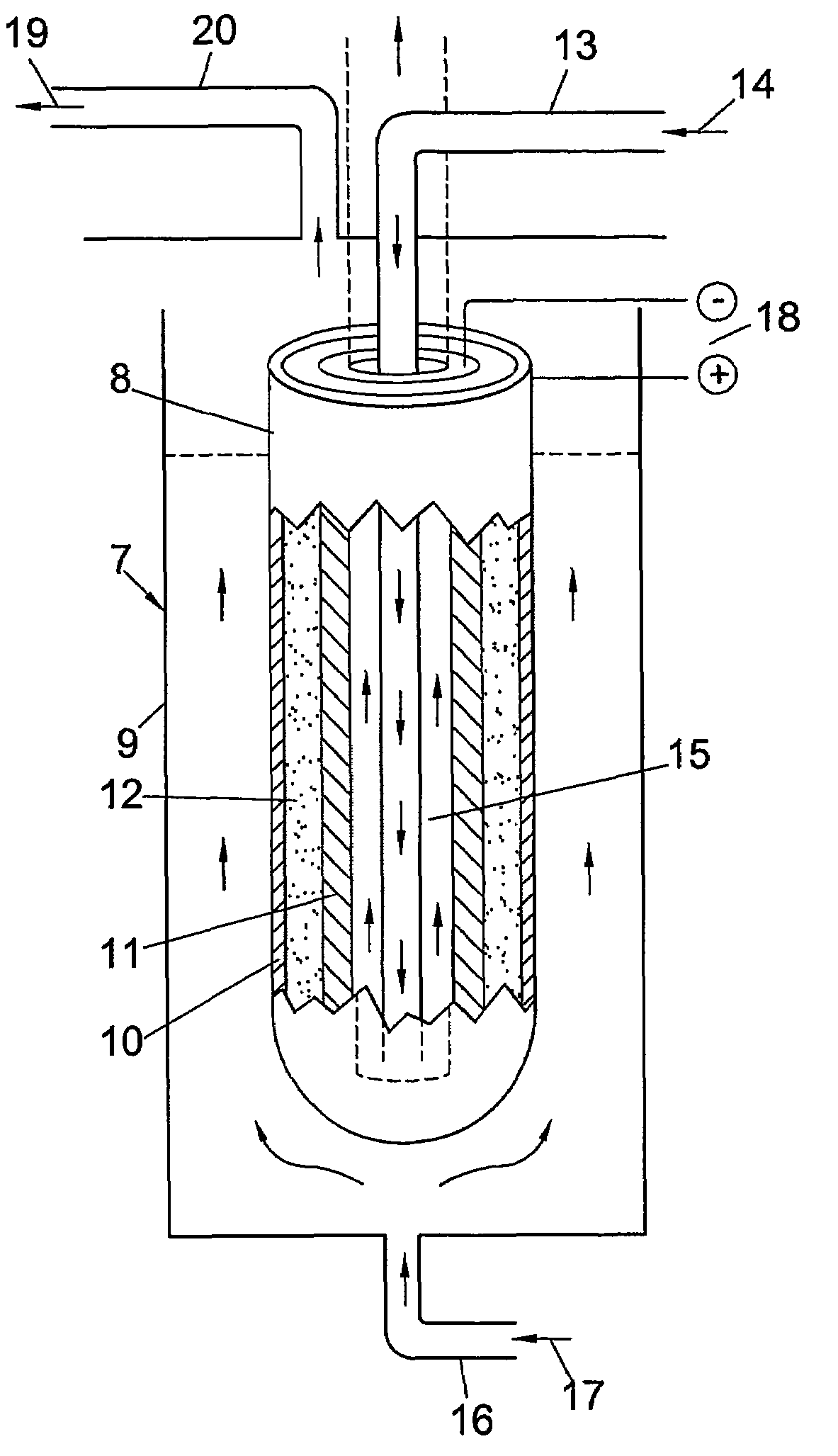
  • Perovskite-based fuel cell electrode and membrane
  • Perovskite-based fuel cell electrode and membrane

Examples


example 1

Preparation of Double Perovskite Material

[0040]La2O3 (4.8873 g), SrCO3 (1.4763 g), Cr2O3 (1.5199 g) and MnO2 (1.7388 g) in powder form were mixed together in an agate mortar. The mixed powders were transferred into a zirconia container, with addition some acetone or ethanol and ball-milled for 15 minutes twice, and then left for 10 hours in a fume cupboard to evaporate the organic component.

[0041]The dried powders were then subjected to a series of high temperature firing and intermediate grinding cycles using a muffle furnace, as follows:[0042]1. 12 hours at 1400° C.[0043]2. 20 mins grinding[0044]3. 12 hours at 1400° C.[0045]4. repeat 2&3 once

[0046]The above procedure yielded 9 g of a double perovskite in the form of a powder having the composition La0.75Sr0.25Cr0.5Mn0.5O3 (LSCM). This phase exhibits a rhombohedral unit cell, a=5.4562(3) Å, α=60.440 (9)°.

example 2

Preparation of Double Perovskite Material

[0047]La2O3 (4.8873 g), SrCO3 (1.4763 g) and MnCO3 (2.299 g) were dissolved in dilute nitric acid (40 mls 4 N) and heated to 80° C. with stirring until a solution is obtained. Then 8.0028 g Cr(NO3)3.9H2O was dissolved into the solution. 25 ml pure ethyl glycol was then added into the mixed nitrate solution and stirred at 80° C. for 2 hours. The obtained gel was transferred into a porcelain container and heated on a hot plate until firing into char. The char was further heated at 1100 to 1400° C. to obtain the perovskite oxide having the composition La0.75Sr0.25Cr0.5Mn0.5O3.

example 3

Manufacture of Anode

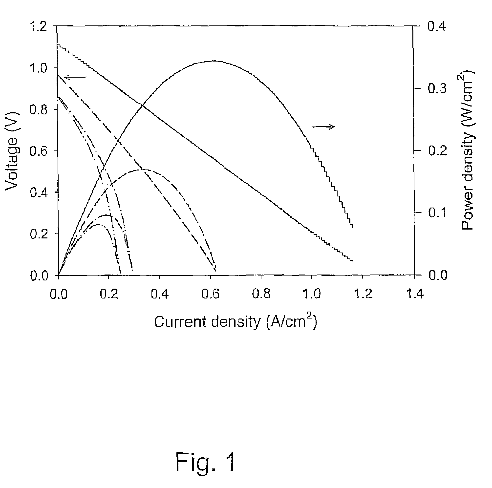
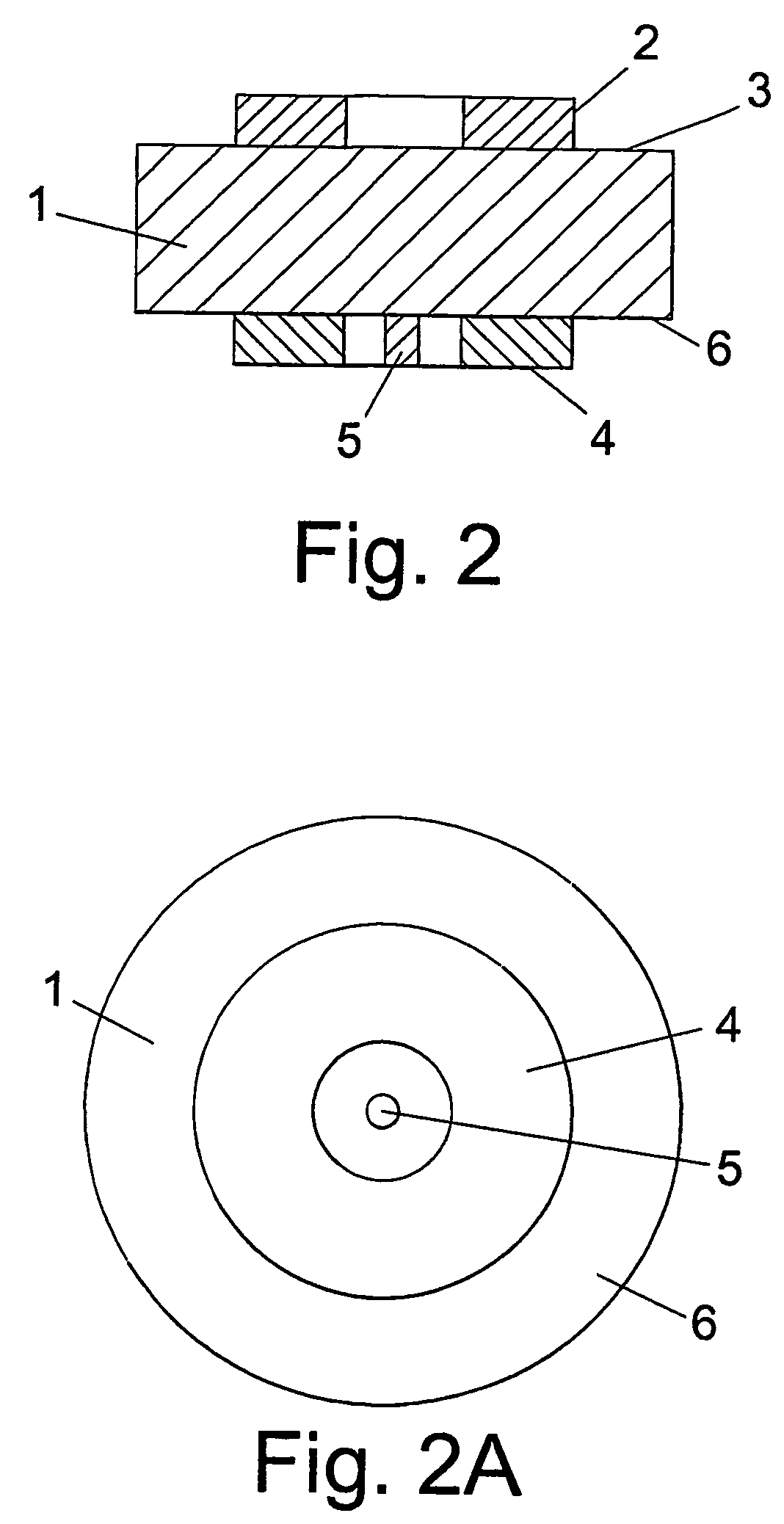
[0048]The double perovskite material of Example 1 (0.45 g) was mixed with 0.05 g carbon (graphite) and 5 ml ethanol. The mixture was ground in an agate mortar or ball-milled for 30 minutes to form a slurry. The slurry was painted or screen-printed onto an 8 mol % Y2O3 stabilised zirconia (YSZ) 2 cm diameter disc with 2 mm thickness. The anode supported on the YSZ electrolyte was then fired from room temperature heating up at 5° C. / min up to 1100° C., held at 1100° C. for 4 hours, and then cooled down to room temperature at 5° C. / min. The thickness of the anode so obtained is about 30-100 μm with an area of 1 cm2. A small amount of gold paste was partially coated onto the anode (ca. 50% coverage) and fired at 900° C. for 30 minutes using a 5° C. / min heating up and cooling down rate in the range from 300° C. to 900° C., to ensure better electronic contact for testing purposes. Platinum paste (Engelhard Clal 6082) was painted onto the opposite side of the YSZ pellet...


PUM

PropertyMeasurementUnit
porosityaaaaaaaaaa
porosityaaaaaaaaaa
thicknessaaaaaaaaaa

Abstract

The present invention provides a material suitable for use in a solid oxide fuel cell, wherein the material is of an, optionally doped, double perovskite oxide material having the general formula (I): (LnaXb)e(Z1cZ2d)fOg (I) wherein Ln is selected from Y, La and a Lanthanide series element, or a combination of these and X also represents an element occupying the A site of a perovskite oxide and is selected from Sr, Ca and Ba, and Z1 and Z2 represent different elements occupying the B site of a perovskite oxide and are selected from Cr, Mn, Mg and Fe, and wherein a has a value from 0 to 1, preferably 0.7 to 1.0, b has a value of from 1 to 0, preferably 0.3 to 0, and each of c and d has a value of from 0.25 to 0.75, provided that a+b has a value of 1, and c+d, has a value of 1, and wherein e has a value of from 0.8 to 1, wherein f has a value of from 0.8 to 1, and g has a value of from 2.5 to 3.2. Also provided are SOFCs having an electrode or functional layer of a material or containing a material of the invention, as well as mixed ionic / electronic conducting membranes suitable for use in a syngas reactor or oxygen separator, comprising a layer of a double perovskite material of the invention, and a method of oxidising a fuel in an SOFC having an anode of a double perovskite material of the invention.

Description

FIELD OF THE INVENTION[0001]The present invention relates to fuel cell electrodes, and more particularly to electrodes suitable for use in solid oxide fuel cells (SOFCs).BACKGROUND OF THE INVENTION[0002]There is a great need for and interest in more efficient means of converting chemical energy into electrical energy, which has created great interest in fuel cells. The practical commercial development of these has, though, been held back by numerous practical problems. The SOFC is a particularly attractive system, which can utilize hydrocarbon fuels such as methane with internal reforming of the fuel, and achieve relatively high efficiencies. Significant problems remain, though, in relation to inter alia the design of the anode used.[0003]Many different materials have been tried in the search for improved anode performance, including materials such as Ni / YSZ (YSZ=Y2O3 / ZrO2) which has relatively good performance but suffers from the substantial disadvantage of relatively short workin...

Claims


Application Information

Patent Timeline
Patent Type & Authority Patents(United States)
IPC IPC(8): H01M8/12H01M8/10C04B35/50B01D53/22C01F11/02C01G37/14C01G45/00C01G45/12C04B35/01C04B35/03C04B35/42H01M4/86H01M4/88H01M4/90
CPCB01D53/228C04B35/016C04B35/42H01M4/8885H01M4/9033H01M8/1246C04B2235/3208C04B2235/3213C04B2235/3215C04B2235/3224C04B2235/3225C04B2235/3227C04B2235/3241C04B2235/3262C04B2235/3265C04B2235/3267C04B2235/76C04B2235/761C04B2235/768H01M2004/8684H01M2008/1293Y02E60/521Y02E60/525Y02E60/50Y02P70/50
Inventor IRVINE, JOHN THOMAS SIRRTAO, SHANWEN
Owner THE UNIV COURT OF THE UNIV OF GLASGOW
Learn More