Data recovery method and data recovery circuit

a data recovery and data technology, applied in the field of data recovery method and data recovery circuit, can solve the problems of increasing chip size, increasing power consumption, and cdr circuit incorporating such a high-frequency vco, and achieves the effect of accurate data recovery, preventing adverse effects of jitter, and easy data recovery process

Active Publication Date: 2010-03-23
RICOH KK
View PDF12 Cites 25 Cited by
  • Summary
  • Abstract
  • Description
  • Claims
  • Application Information

AI Technical Summary

Benefits of technology

[0015]The present invention is conceived in view of the above-described problems, and it is an object of the present invention to provide a data recovery technique for accurately restoring data using an independent clock at or below clock frequency of the input data, instead of recovering clocks contained in the input data, under less influence of jitter even if jitter is contained in the input data.
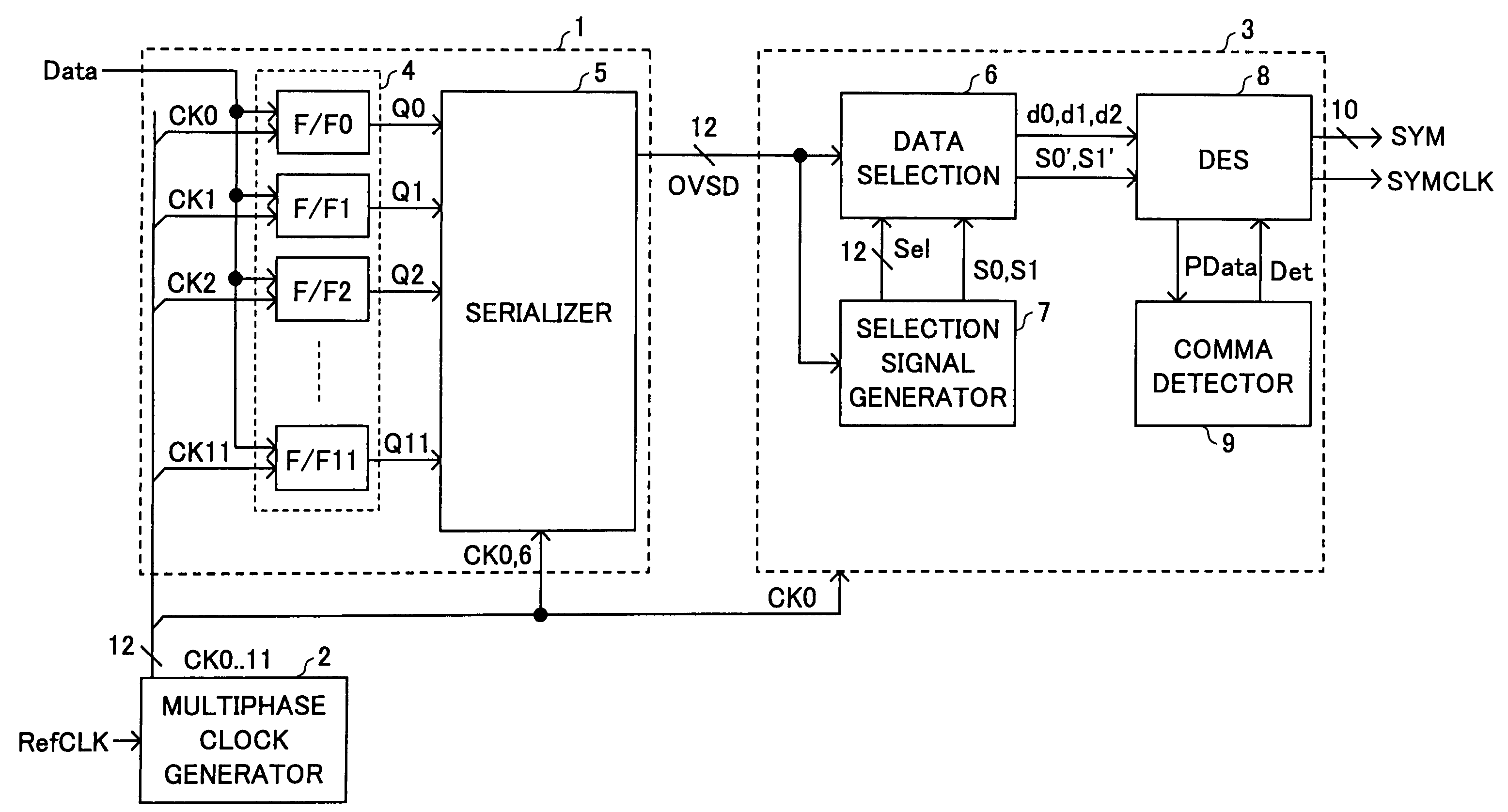
[0020]In this manner, the serially transmitted data sequence is oversampled using a multiphase clock of frequency f2, which frequency is at or below clock frequency f1 contained in the serially transmitted data, without directly using the data transmission clock f1. A prescribed number of bits are extracted from the oversampled data, taking the phase deviation due to frequency difference into account. Consequently, the data recovery process can be carried out easily even at a high transmission rate, while preventing adverse effect of jitter, and accurate data recovery is realized.
[0021]With the data recovery method and circuit, a separate clock independent of the data transmission clock is used to oversample the received data. In addition, the received data are recovered using the clock pattern with the same period as that of the transmission clock contained in the received data, while shifting the phase of the clock pattern. Consequently, there is little influence of frequency difference and / or jitter on the recovered data. Because the frequency f2 of the multiphase clock can be set to a fraction of clock f1 of the received data, the circuit can easily respond to a rise in data transmission rate.

Problems solved by technology

The CDR circuit incorporating such a high-frequency VCO has some negative effects, including increased chip size, increased power consumption, and increased cost.
In addition, wiring-induced clock delay cannot be ignored in such a situation where further speed-up of data transmission is required, and sufficient consideration has to be given to wiring layout and device arrangement.
As a result, the circuit design becomes more complicated.
Thus, the reusability of the circuit is degraded, and the development period becomes long.
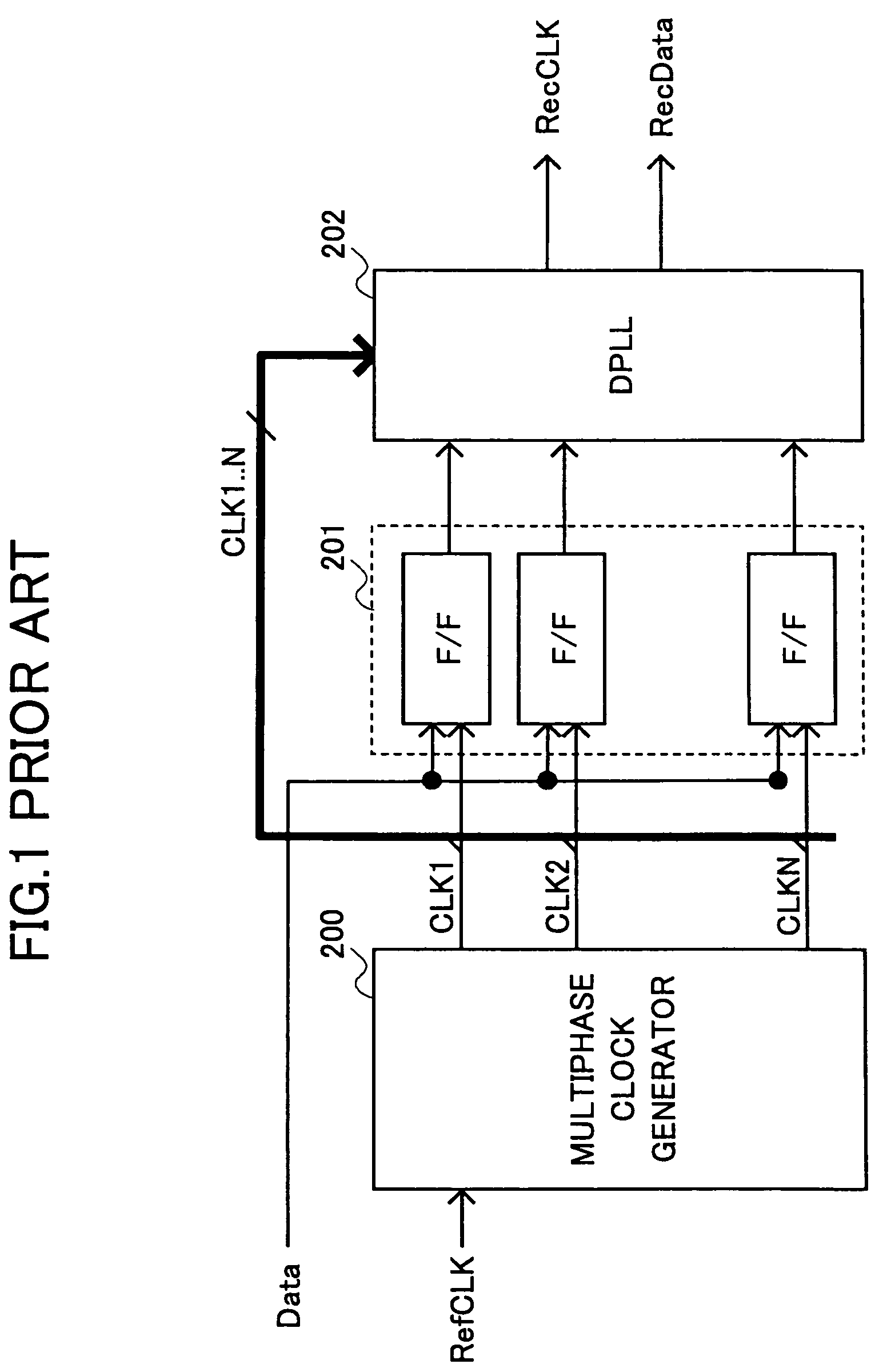
However, the phase difference among the multiple clocks has to be controlled precisely because uneven phase difference may introduce errors.
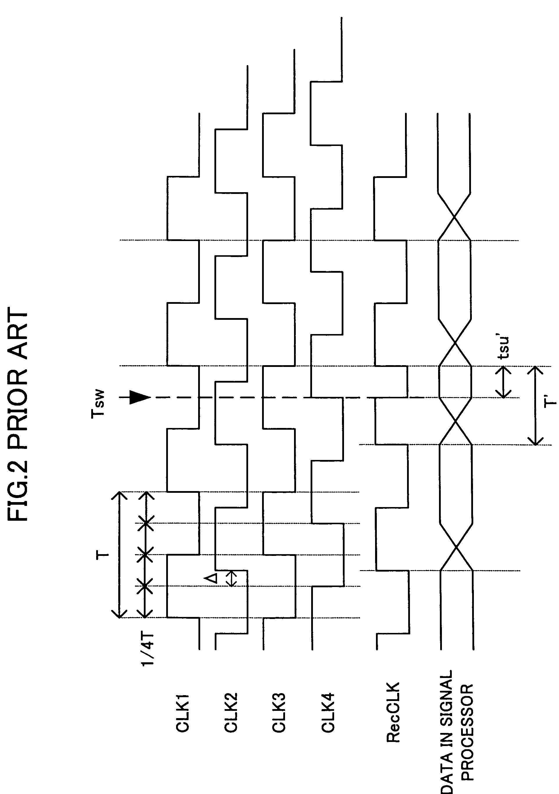
Consequently, time Tsu′ required to set up the flip flop in the signal processor cannot be guaranteed, and in the worst case, errors occur.
In this case, variation in delay among multiple clocks has to be eliminated at each site; however, such elimination is very difficult and has not been realized yet.
However, the circuit scale becomes large, and the wiring delay due to high-speed operation cannot be ignored.
The wiring delay could be avoided by correcting the phases of the multiple clocks every input stage; however, this method is as difficult as implementing an oversampling CDR circuit that operates at oversampling frequency (which is four times the clock frequency of the transmitted data in the example shown in FIG. 2).
Thus, for those apparatuses using a conventional CDR circuit with an analog PLL or an oversampling CDR circuit to recover the clock from the input data to conduct signal processing based on the recovered clock, the development period becomes longer and longer as the transmission rate increases because CDR design becomes more difficult.

Method used


Image

  • Data recovery method and data recovery circuit
  • Data recovery method and data recovery circuit
  • Data recovery method and data recovery circuit

Examples


first embodiment

[0049]FIG. 3 is a schematic block diagram illustrating serial data transmission to which a data recovery circuit is applied according to the first embodiment of the invention.

[0050]The physical layer 100 includes a transmitter 101 for transmitting data and a receiver 102 for receiving data. Data are transmitted and received to and from another physical layer 120 having a pair of transmitter 122 and receiver 121, via transmission lines 106 and 107. The physical layer 100 has a PLL 113 for generating a clock of frequency f2 from a reference clock RefCLK 1. The physical layer 120 has a PLL 123 for generating a clock of frequency f1 from a reference clock RefCLK 2. The physical layers 100 and 120 operate at frequencies f2 and f1 produced by the PLLs 113 and 123, respectively. The pair of transmitter 101 and receiver 102, and the pair of transmitter 121 and receiver 122 are called ports. Serial data transmission is performed between the ports by point-to-point.

[0051]The transmission line...

second embodiment

[0152]The second embodiment of the present invention is now described. In the second embodiment, the selection signal generator 7 and the data selector 6 used in the symbol data restoration unit 3 of the first embodiment are modified, and the other structures are the same. Accordingly, explanation is made focusing on the selection signal generation and data selection.

[0153]FIG. 21 is a block diagram of the selection signal generator used in the data recovery circuit according to the second embodiment of the invention. In the selection signal generator shown in FIG. 21, signals output from the counter 61, the state controller 62, and the selection signal converter 63 are different from those illustrated in the first embodiment in FIG. 6. The other components, that is, the both edge detector 20, the comparator 21, the CKP converter 24, and the edge detector 25 are the same as those shown in the first embodiment. The same components with the same functions as those of the first embodim...


PUM


Abstract

A data recovery method includes the steps of:(a) oversampling data that have been transmitted serially in sync with a first clock of frequency f1, using a multiphase clock generated by shifting a phase of a second clock of frequency f2 at a prescribed interval, the second frequency f2 of the multiphase clock being at or below the first frequency f1; (b) extracting f1 / f2 bits on average from the oversampled data; and(c) recovering the extracted bits to restore the received data.

Description

BACKGROUND OF THE INVENTION[0001]1. Field of the Invention[0002]The present invention relates to a data recovery method and a data recovery circuit for restoring serially transmitted data.[0003]2. Description of Related Art[0004]In recent years and continuing, various types of high-speed interface standards have been proposed and put into practical use in order to respond to demand for high-speed data transmission. Examples of such interface standards include USB (Universal Serial Bus), Serial ATA (Advanced Technology Attachment), IEEE 1394, 1G / 10G Ethernet (Registered trademark), InfiniBand, RapidIO, Fibre Channel, and PCI (Peripheral Component Interconnect bus) Express. It is expected that more and more emphasis will bw put on higher-rate and large-capacity data communication in the future.[0005]Most of the high-speed interfaces employ serial transmission schemes for transmitting data according to a predetermined frequency. A clock of that frequency is embedded in the transmitted ...

Claims


Application Information

Patent Timeline
Patent Type & Authority Patents(United States)
IPC IPC(8): H04L7/00H04L7/033H04L25/08
CPCH04L7/0338
Inventor MASUI, NARUHIROEMA, HIDETOSHI
Owner RICOH KK
Why Eureka
Try Eureka