Fishtail bore seal

a technology of bore seals and fishtails, applied in the direction of borehole/well accessories, cable terminations, hose connections, etc., can solve the problems of low carbon steels that have limited resistance to extremely corrosive wells, exceed seal yield, and permanent compressive strain, etc., to resist aggressive corrosive conditions and higher temperatures, and resist external pressure

Inactive Publication Date: 2010-10-26
SUB DRILL SUPPLY
View PDF26 Cites 15 Cited by
  • Summary
  • Abstract
  • Description
  • Claims
  • Application Information

AI Technical Summary

Benefits of technology

[0022]A primary object of the invention is to provide a bimetal bore seal, and method of manufacturing same, for sealing connections between oil and gas well tubular members that has the material properties capable of resisting aggressively corrosive conditions and higher temperatures encountered in deeper oil and gas wells, and also resisting external pressure in deep seawater.
[0024]Another object is to provide a bimetal bore seal which has a good strength retention in order to enable the bore seal to operate within its elastic limit and thus maximize its service temperature range.
[0026]Another object is to provide a bimetal bore seal constructed to resist stress corrosion cracking caused by acid gases dissolved in the liquid phase.
[0028]Another object is to provide a bimetal bore seal with a high strength, high hardness metal core and a corrosion resistant metal coating, which is applied by a thermal spray process to a hardness that is lower than the hardness limit specified by NACE International.

Problems solved by technology

Generally, the preload stress in the bore seal exceeds yield and causes some permanent compressive strain.
The low carbon steels have limited resistance to extremely corrosive well conditions.
Bore seals made of low carbon steel or the 300 series stainless steels, being at or close to yield at preload, may suffer an increase of permanent compressive strain during service due to bore diameter changes from rises in temperature and pressure fluctuations.
Increases of permanent strain brought about by operating conditions will reduce the contact force created between the seal and seat when the connection was preloaded, although this is unlikely to affect performance if bore pressure and temperature are substantially maintained.
However, if the bore pressure and temperature are greatly reduced, the reduction of the diametral interference between seal and seat may result in failure of the connection to retain pressure.
This requirement, however, limits the hardness of the bore seal and consequently its material strength.
Furthermore, this hardness limitation is in direct conflict with the need for adequate yield strength to resist external pressures, as encountered in deep water operations.
However, as a result of unforeseen behavior in the formation being drilled, a sudden loss of bore pressure to a value below the external pressure can occur.
The low carbon and series 300 stainless steel designs, however, cannot function reliably against external pressure because their low strength levels make them prone to incremental permanent strain due to operational variations of pressure and temperature.
However, coatings of this type are not durable enough to resist abrasion and corrosion for more than a short period of time.
However, electroplated metals such as silver, lead, zinc, cadmium or copper can be applied in a thickness range of only 12 to 25 microns and are therefore unable to resist corrosion or abrasion for more than a short period of time.
While electrodeposited nickel can be deposited in thicknesses that will withstand corrosion for extended periods, such material is unsuitable for bore seals because of its extreme hardness and difficulty of machining.
While lubricating compounds can be successfully applied, e.g. Teflon® in multiple applications to a thickness of 50 to 60 microns and molybdenum sulfide to 8 to 12 microns, they are also unable to resist abrasion and corrosion for more than a short period of time.
Welding a corrosion resistant inlay onto the bore seal surface solves some of the previously discussed problems; however, it is not an ideal solution.
As a partial deposit on the sealing surfaces, the interface between the steel body and welded corrosion resistant alloy inlay may be subject to crevice corrosion.
After the corrosion resistant or lubricant coating which is applied over the partially welded gasket has eroded, accelerated corrosion could occur due to bimetallic contact with aqueous electrolyte.
Furthermore, in some cases, where the inlay has a high thermal expansion the bore seal may act as a bimetallic strip causing its tips to flex away from the seat areas.
Partial or complete weld coverings have additional potential disadvantages when used to protect and / or strengthen the bore seal core materials.
The process of weld deposition generates extreme heat that may affect the mechanical properties of the core bore seal material.
The extreme heat may also cause changes to the physical shape of the core bore seal material which can result in post-weld difficulties in machining the bore seal to an accurate shape profile.
As previously indicated, crevice corrosion between the weld lines of the bore seal core material and the corrosion resistant inlay may also become apparent over time, especially if there are any imperfections in the welds.
Coupled with this, higher temperatures and more aggressive corrosive conditions are encountered as drilled depths increase.
However, a major drawback to the prevalent use of these nickel alloys is their expense.
Constructing a metal bore seal completely from a corrosion resistant nickel alloy would solve some of the problems previously discussed, however, such construction would be cost prohibitive in many applications.

Method used


Image

  • Fishtail bore seal
  • Fishtail bore seal
  • Fishtail bore seal

Examples


Embodiment Construction

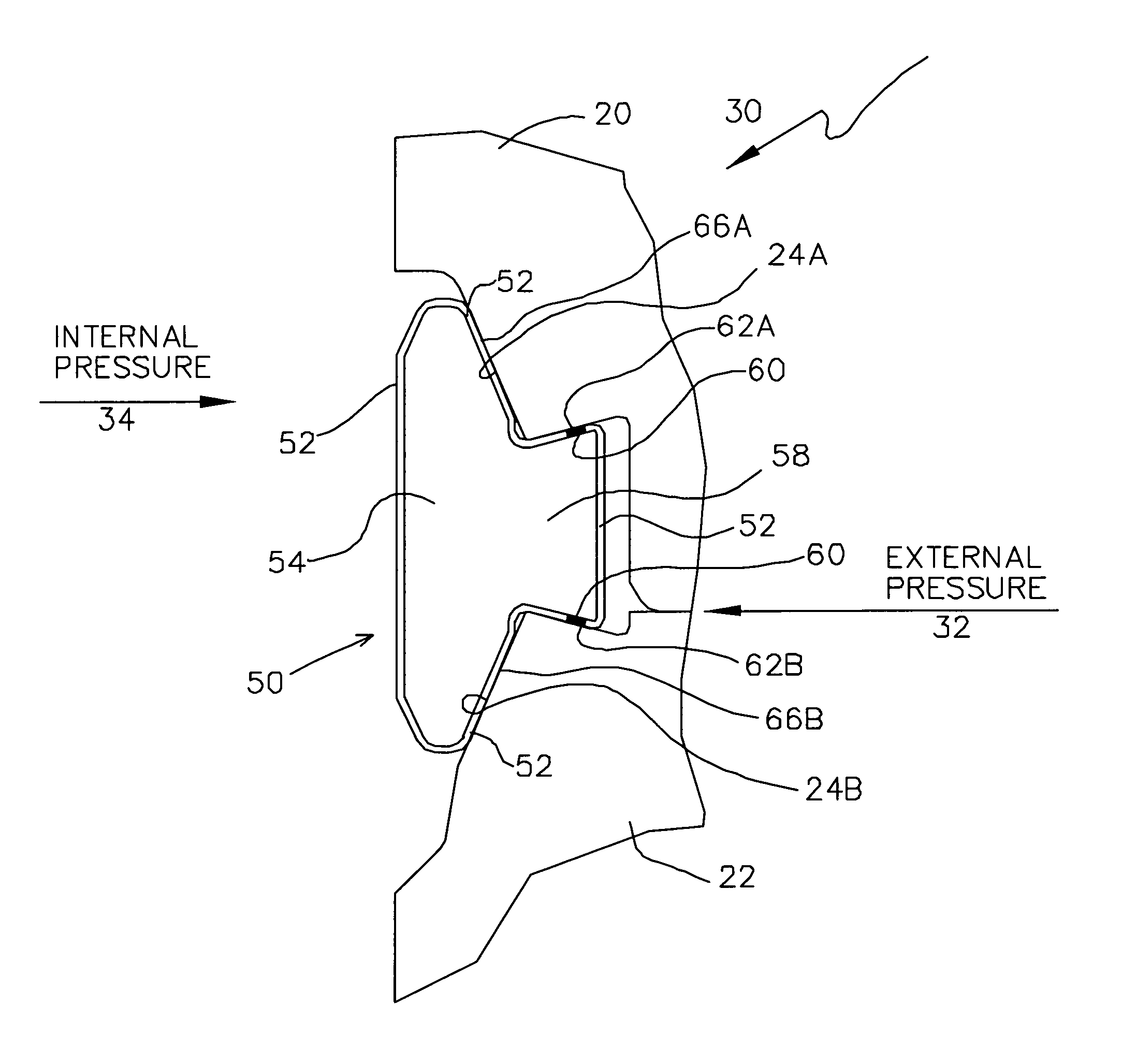
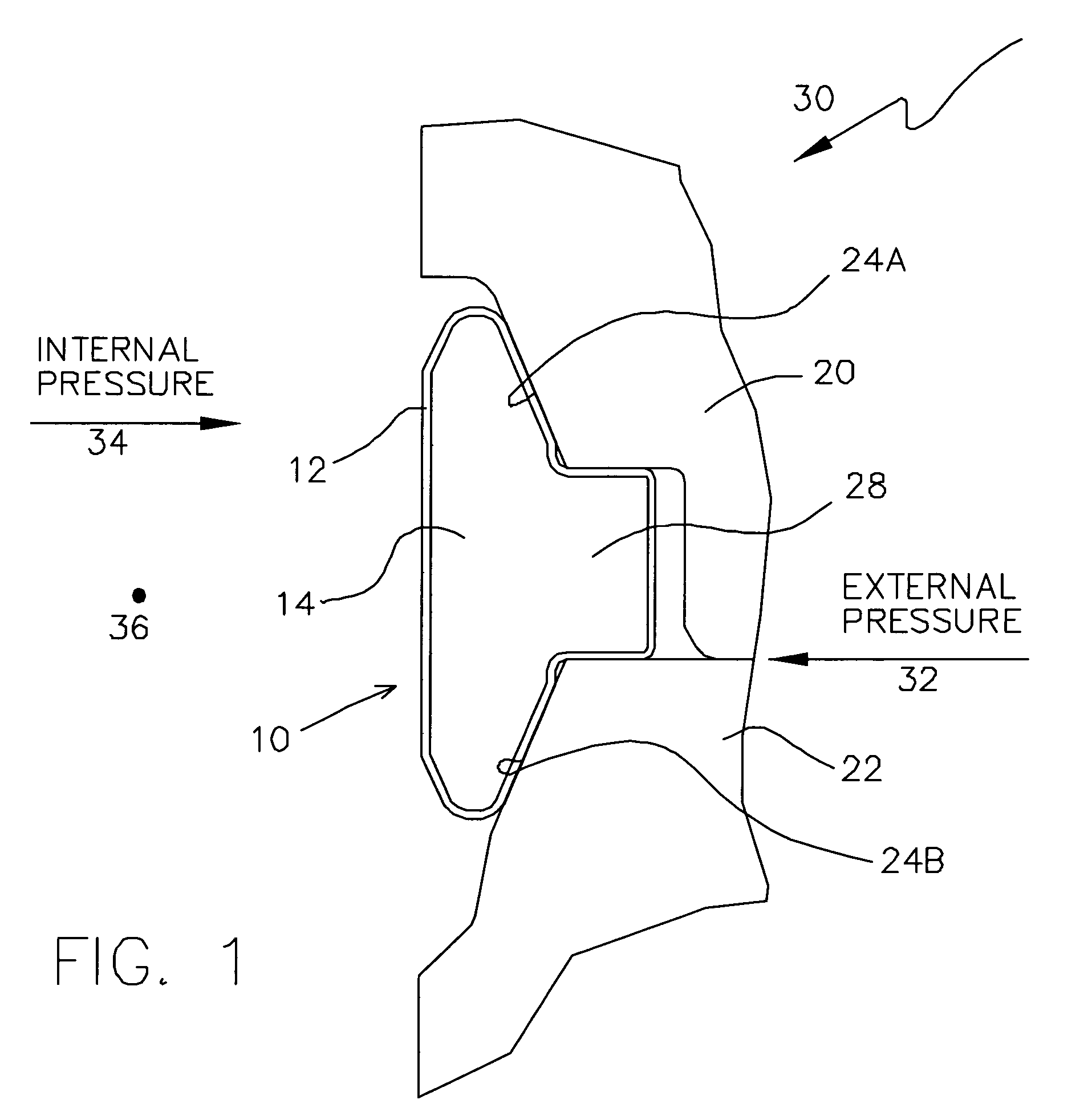
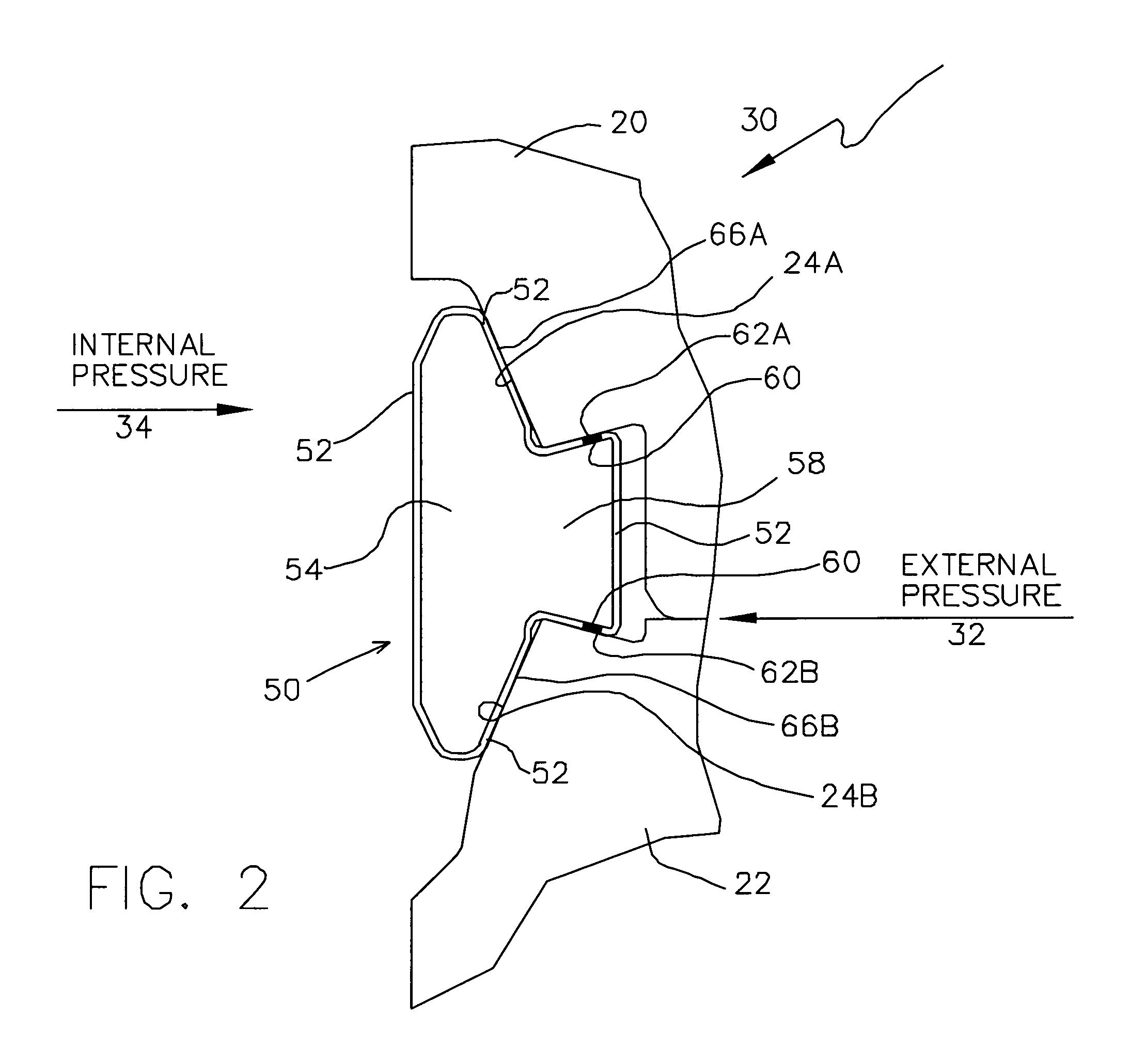
[0038]The preferred embodiment of the invention is a bore seal which alleviates one or more of the deficiencies described in the prior art and incorporates one or more of the objects previously identified. The bore seal of the present invention is a compression ring disposed and compressed between the opposing ends of the oil and gas well tubular members to be joined. The bore seal of the preferred embodiment has an internal diameter / shape arranged and designed to match the bores of tubular members and equipment to be joined and sealed, including commercially available profiles, such as AX, CX, DX, LX, NX, VX, etc. The ring is about four inches long (measured in its axial direction) and is machined externally to provide two conical faces tapering towards each end at about a twenty-three degree angle to the axis. The ends of the connecting components are machined to open outwardly in order to provide tapering conical seats for the ring at the same angle but with a slightly smaller di...


PUM

PropertyMeasurementUnit
yield strengthaaaaaaaaaa
temperaturesaaaaaaaaaa
bore pressuresaaaaaaaaaa

Abstract

A bore seal for connecting and sealing oil and gas tubular members is disclosed which has a metal core manufactured from a high yield strength ferrous material and a protective overlay of corrosion and abrasion resistant stainless steel and / or nickel based alloy. The protective overlay is applied to the entire outer surface of the bore seal by a metal thermal spray process, such as plasma thermal spraying. In a preferred embodiment of the invention, the bore seal has a fishtail profile which facilitates the use of resilient seals to provide resistance to external pressures in addition to the traditional metal-to-metal seal between the bore seal and the tubular members. In an alternative embodiment, a pressure relief valve is disposed within the bore seal to verify the integrity of the metal-to-metal seal with respect to internal bore pressure.

Description

BACKGROUND OF THE INVENTION[0001]1. Field of the Invention[0002]This invention relates to metal bore seals for sealing connections between oil and gas well tubular members and other equipment in sub-sea drilling and production operations. More specifically, the invention relates to a corrosion-resistant bimetallic compression ring designed for both well pressure containment and deep water pressure resistance.[0003]2. Description of the Prior Art[0004]Many oil and gas fields are situated offshore at various ocean depths. In the oil and gas exploration and production industries, the underwater connection between the wellhead and the rig or platform is achieved by sequentially joining together items of drilling and production equipment, as well as long segments of metal and composite pipes, or riser joints, to form a pressure tight system. Metal bore seals (or gaskets) are commonly used to create and maintain the requisite pressure tight seal at the joints. These bore seals therefore p...

Claims


Application Information

Patent Timeline
Patent Type & Authority Patents(United States)
IPC IPC(8): F16L19/06
CPCE21B17/02E21B17/04F16J15/0806F16J15/0887E21B33/1208E21B33/1212E21B33/128E21B17/046
Inventor PATON, ALAN STEWARTROOTS, PHILIP STANLEY
Owner SUB DRILL SUPPLY
Why Eureka
Try Eureka