Autofluorescence imaging system for endoscopy

Inactive Publication Date: 2010-12-07
HOYA CORP
View PDF67 Cites 34 Cited by
  • Summary
  • Abstract
  • Description
  • Claims
  • Application Information

AI Technical Summary

Benefits of technology

[0012]The system of the present invention has the ability to switch back and forth between white light and fluorescence visualization methods electronically, requiring no moving parts within the endoscope itself The elimination of cameras and imaging optics at the proximal end of the endoscope significantly improves its handling characteristics. A computer-based imaging system allows quantitative images of the tissue to be displayed, at refresh rates of up to 10 Hz or higher, for example. A preferred embodiment uses easily seen, false-color overlays which indicate the likely areas of tissue dysplasia. By “false color” we mean that a color value is assigned to a particular level of fluorescence intensity for each pixel. A data processing system can be programmed to provide a color system suitable for imaging a given type of tissue condition. The system can be used either with color wheel (e.g., using a monochrome CCD) video endoscopes or with color imaging sensor endoscopes.
[0013]In a preferred embodiment, near ultraviolet light is chosen as the excitation wavelength, as described in Wang, et al., U.S. Provisional Application No. 60/072,455, Jan. 26, 1998. This choice in the range of 300-420 nm reduces or eliminates the need for addit

Problems solved by technology

Visual inspection is less effective in detecting the superficial lesions of flat dysplasia, such as ulcerative colitis and Barrett's esophagus.
Only a very small fraction of a large surface, such as the colon, can be surveyed in this manner and small areas of dysplasia may go undetected.
The application of these drugs takes additional time and has the potential of causing adverse side effects.
Point detection instruments have the advantage of providing more complete spectral information on the tissue, but are too slow for routine screening of large tissue areas and may mis

Method used


Image

  • Autofluorescence imaging system for endoscopy
  • Autofluorescence imaging system for endoscopy
  • Autofluorescence imaging system for endoscopy

Examples


Embodiment Construction

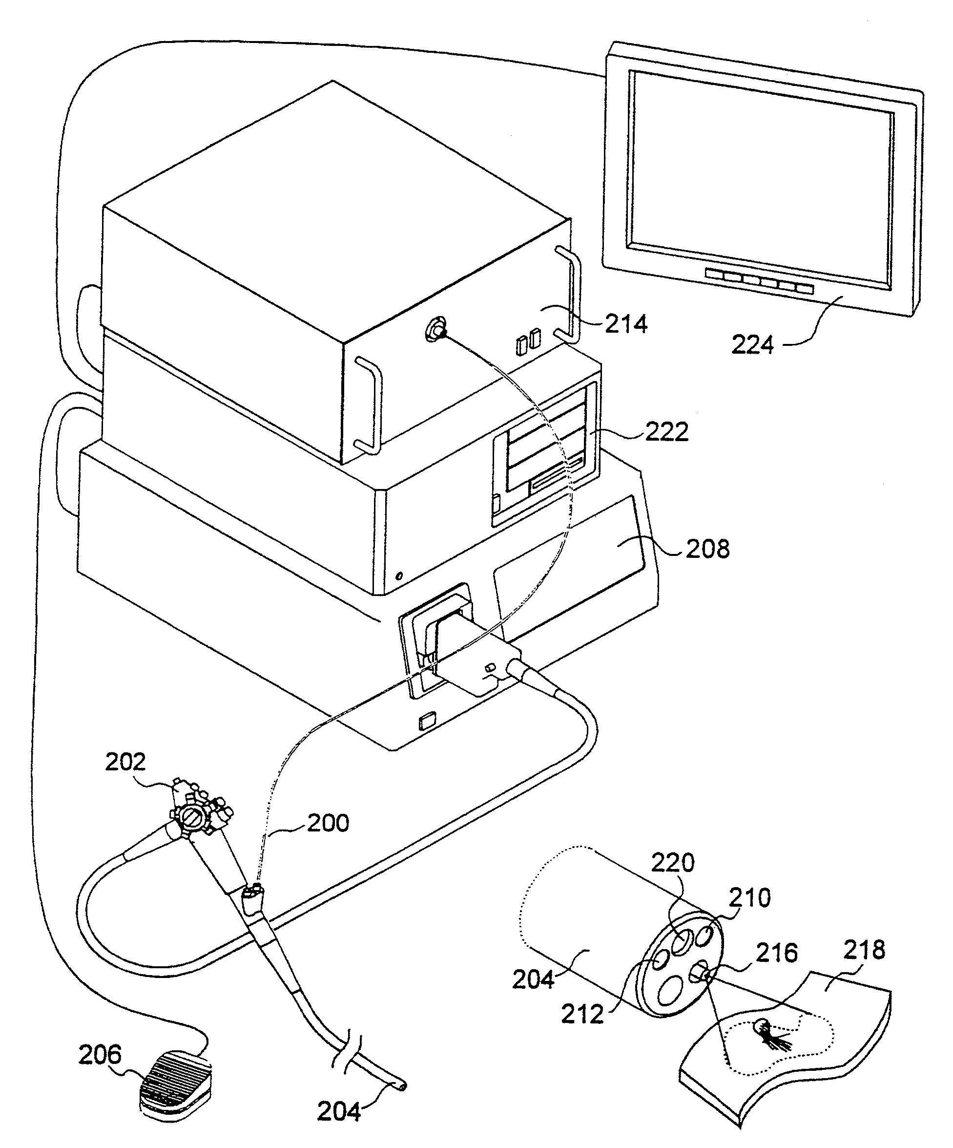
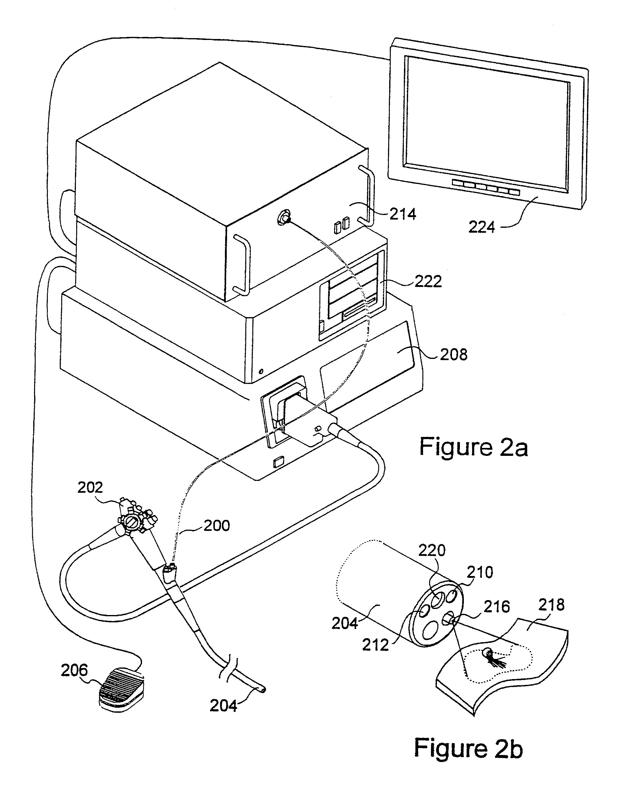
[0027]The present invention relates to systems and methods for imaging autofluorescence from epithelial tissue to highlight regions of dysplasia. The tissue autofluorescence imaging system in accordance with the present invention improves upon the previous state of the art in that, in its simplest form, it can be added on to an existing video endoscope system with no modifications to the endoscope itself, and with only the addition of a shutter in the optical path of the endoscope's visible light source. The handling characteristics of the endoscope are thus not adversely affected by the addition of image intensifiers and external cameras at the proximal end as required by fluorescence imaging systems currently on the market. Switching between normal visible light imaging, in full color, and fluorescence imaging is accomplished by an electronic switch rather than a physical manipulation by the clinician, also required by current systems. The resulting fluorescence video image is pro...


PUM


Abstract

A system and method for imaging tissue autofluorescence through a video endoscope is described, comprising a light source capable of providing both ultraviolet light capable of inducing tissue autofluorescence and visible light which induces little or no autofluorescence, an optical system to deliver both wavelength bands to the tissue with the same apparent spatial and angular intensity distribution, a means for digitally acquiring the resulting, visible fluorescence and visible reflectance images using a single imaging detector at the distal tip of the endoscope and a means for digitally processing said images to generate a final, false-color image for display which indicates regions of tissue dysplasia. This system can either be added on to an existing video endoscope or integrated into its structure. The combined system can be electronically switched between normal white light imaging and fluorescence imaging.

Description

RELATED APPLICATION[0001]This is a continuation of U.S. application Ser. No. 09 / 362,806 filed on Jul. 28, 1999, now U.S. Pat. No. 6,364,829, issued Apr. 2, 2002, which is a continuation-in-part of U.S. application Ser. No. 09 / 238,664 filed Jan. 26, 1999, now U.S. Pat. No. 6,537,211, issued Mar. 25, 2003, the entire contents of which are incorporated herein by reference.GOVERNMENT SUPPORT[0002]This invention was supported in whole or in part by a grant from the National Institute of Health, Grant No. R44CA72626, “Imaging Spectrofluorimeter for Colonic Dysplasia”. The Government has certain rights in the invention.BACKGROUND OF THE INVENTION[0003]Advanced stage cancers are difficult to treat effectively, so it is important to detect them in their premalignant stages, such as dysplasia or carcinoma in situ. Currently, the most widely used method for early detection uses visual inspection trough endoscopes, which relies upon the recognition of the gross architectural changes associated ...

Claims


Application Information

Patent Timeline
IPC IPC(8): A61B1/06A61B6/00A61B1/00A61B5/00G01N21/64
CPCA61B1/00009A61B1/00126A61B1/043A61B1/0638A61B1/07A61B5/0071A61B5/0084A61B1/0646A61B1/0669A61B1/0655
Inventor FULGHUM, STEPHEN F.
Owner HOYA CORP
Why Eureka
Try Eureka